Calling down the lightning
Posted: January 16, 2026 Filed under: Art, Coding, Creations, DIY, Explorations, How-to, That Totally Worked | Tags: arduino, attiny, blinky, burning man, DIY, electronics, fastled, Halloween, LED, LEDs, light, lightning, MOSFETs 1 CommentSo here was the big idea: a bunch of umbrellas with lightning in them. Like this:

Sianna and Dean and I started brainstorming about this as an idea for an art project for Burning Man 2018, and as these things do, the idea quickly blew up from a simple idea to include all kinds of complicated and awesome details.
The original idea was something like:
- umbrellas
- plain, always-on LED strings (cool white) sewn into the umbrellas
- use the pre-wired 3xAA battery pack that comes with the LED strings
Here’s where we wound up after a bunch of brainstorming:
- umbrellas
- four independent strings of LEDs (cool white) sewn into each umbrella, so that there could be animation and motion
- microcontroller programming of the LED strings, to create the flashes and motion
- some other sort of battery setup, not just the plain 3xAA battery pack that came with each LED string
- synchronization of the whole pack of umbrellas together, so that lightning could flash across all of the umbrellas at once, or across them in some kind of fast sequence
Sianna and Dean did all the sewing of the LEDs into the umbrellas, and I did the electronics design, construction, and programming.
What follows is the story of how I arrived at the final electronics design for these “stormbrellas”. I started with an initial electronics design for each umbrella that required some kind of full Arduino board plus a custom PCB ‘shield’ with a literally a dozen discrete components on each board to drive the LED strings. Then, through some outside-the-box thinking, some semi-careful / semi-brave experimentation, and progressive refinement I wound up with a design that required a total of just three discrete components to control each umbrella — and no “Arduino” board.
I am not a big expert at this sort of electronic design project, so a great deal of this was new territory for me. I’m hoping that you find this story interesting, and that perhaps it inspires you to try something new in this area, as well.
The Naive Design
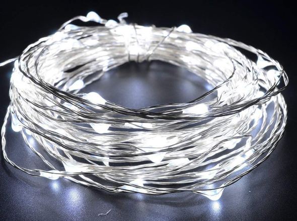
The LED strings that we were using were the kind with ‘grain-of-rice’ LEDs mounted on barely-insulated bare metal wire, like this.
I wanted to use an Arduino (of some sort) to control the strings of LEDs, because I know it pretty well, and I already had a bunch of them lying around waiting to be used in projects.
Power to the pixels
I know that you can power individual LEDs directly from the ‘output’ pins of an Arduino, by connecting the LED from the output pin, through a (very important!) current-limiting resistor, to Ground. There’s a famous sort of joke in electronics that if you omit the current-limiting resistor, the LED will try to draw more power than it can handle, and in a very short period of time it will turn from a Light-Emitting Diode into a Smoke-Emitting Diode. (See also: “light-emitting resistors”.) So you always always always need to make sure the LEDs can’t draw more power than they can handle, and the way to do that is a current-limiting resistor.
I also know that there’s a limit to how much current you can draw directly from one Arduino pin, and that you definitely cannot run a whole string of LEDs directly from an Arduino output pin. Instead, you need to use a power transistor, like a MOSFET, as a sort of a power switch. The Arduino controls the MOSFET, and the MOSFET switches the high-current power on and off to the LEDs. Each MOSFET needs a ‘pull-down resistor’ to turn it all the way off when it’s not being activated.
Of course each string of LEDs still needed a ‘current-limiting resistor’ as well. When I dissected one of the battery packs that came wired to the LED strings, I found that each one had 3xAA batteries (4.5 volts total), an on/off switch, and a 3.6 ohm current-limiting resistor, all in series with the string of LEDs. These particular LEDs seemed to want something like 3.3 volts across them. The battery pack (3xAA) produced 4.5v, and their simple design just used the small resistor to limit the current, and drop the voltage — throwing away the rest of the energy as heat. And wow did that resistor get hot!
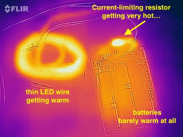
I measured the temperature of the resistor (in open air) at over 140ºF when the LEDs were lit. It was definitely keeping the LED current and voltage down, but it was throwing away a whole lot of the battery power as heat, too. I estimated that nearly 1/3rd of the energy in the batteries was being turned into heat, and only about 2/3rds of the energy was coming out as light. Anyway, clearly the current-limiting resistor was important for these LED strings.
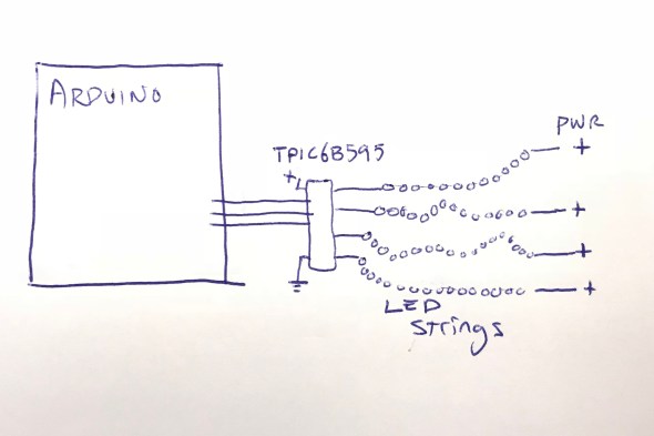
So I figured that I’d want an Arduino board, and then for each string of LEDs, a MOSFET, a pull-down resistor, and a current-limiting resistor, arranged something like this:
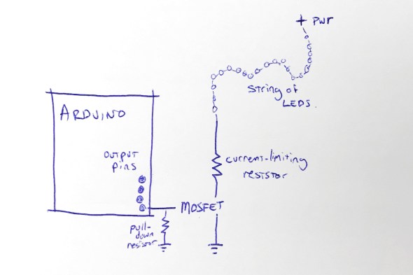
This shows the rough design for controlling one string of LEDs; to control four strings of LEDs, I’d need four MOSFETs, four pull-down resistors, and four current-limiting resistors. I figured that I’d mount all of that on some kind of Arduino ‘prototyping’ shield. Each shield would have those twelve components on it.
Call me lazy (go ahead, I’ll wait), but that seemed like a lot of parts, and a lot of work to build six umbrellas that way.
“Grandfather say ‘It never rain every day'”
I started thinking about those current-limiting resistors, and these LED strings, and about Burning Man, and about lightning itself. To simulate the look of lightning, I was not going to run these LED strings turned on all the time. In fact, they’d be turned off most of the time. I’d only need to power them up for short, bright flashes. And of course, this being Burning Man, the brighter, the better!
I also thought back to this great tech note from Cree (the superbright LED people) entitled “LED Electrical Overstress”, but which I refer to as “So You Want To Run Our LEDs Beyond Their Rated Power Limits”. http://www.cree.com/led-components/media/documents/XLamp_Elec_Overstress.pdf This tech note addresses the question “OK, so if the LED is rated for X volts, what actually happens if I run it at a voltage higher than X, but just for a short time?” And the answer they give is something like this: well, it might be a little bit brighter (but not proportionately), and it will probably also shorten the life of the LED, especially if the LED is over-volted for any significant amount of time.”
And I thought about those tiny little 3.6 ohm current-limiting resistors in the battery wired pack. I wondered if I needed them at all. Maybe I could sneak by without the current-limiting resistors — if I only pulsed the LEDs on for short flashes. And maybe, just maybe, the LEDs would flash brighter than usual, for those short flashes, if I omitted the current-limiting resistors. I decided to try it as an experiment: run the LED strings with no current-limiting resistor. Well, sort of. I say sort of because those LEDs are strung along very long, very skinny wires. And you know what a long, skinny wire acts like? Hint: a resistor.
Well, I tried running one of the LED strings for fifteen minutes solid, at full power, with no (external) current-limiting resistor and here’s what I found: the LED strings do light up a little bit brighter. The wires themselves definitely got warm, but not too hot to touch. I wouldn’t want to run them like that, full-on, for hours… but that’s not the plan. The plan is to flash them on for fractions of a second, or maybe even flicker for a couple of seconds, and then leave them off for a long stretch.
So I decided that since I was just flickering the LED strings on with (much) less than a 10% duty cycle, I could probably skip the current-limiting resistors … and get brighter flashes in return. Win-win.
And in addition to the specific component reduction (and brightness boost), this planted a seed in my head: sometimes you can go beyond the rated limits of a device, especially if you’re only doing it for a short time. Keep this in mind; it shows up again later.
Shifting away from MOSFETs
At this point the design for each umbrella is basically: Arduino + protoshield with four MOSFETS and four pull-down resistors. And of course four LED strings. I didn’t want to juggle the four separate MOSFETs, and I started wondering if there was some pre-packaged integrated circuit that basically had four MOSFETs inside it, so that I could reduce the part count from 4 MOSFETs down to one IC.
Looking around for a while, I came across the TPIC6B595, a “high power shift register”. They’re a bit like the popular 7HC595 shift register, with eight output pins, but they can drain “up to 150mA” per output pin. This might be the chip for me, I thought. But then, Hrm, I wondered, I wonder how much current I need for each LED string. I did some tests and found that each LED string could draw up to about 350mA. 350mA is far more than 150mA, so I didn’t think this chip was going work for me. On a lark, I decided to read the actual datasheet for the chip, from TI: http://www.ti.com/lit/ds/symlink/tpic6b595.pdf And look what we have here (highlighting is mine) …
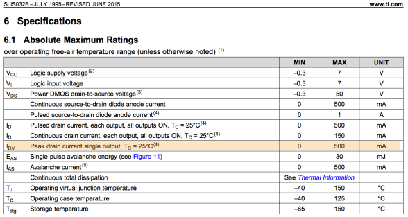
While the continuous drain current is 150mA per output pin, the peak drain current per pin is 500mA! And 500mA is greater than the 350mA that I need to flash the LED strings on for a few instants! Maybe this was the chip for me after all. I ordered one to test. Well, I actually ordered two, because electronics tend to not bounce back well from being tested with current levels above their ratings.
The chip arrived, and I wired it up, found some Arduino code to drive it, and lo and behold, it worked! In fact, I was able to hook up all four LED strings to the TPIC6B595 chip, and light them all up brightly (and briefly!) with no detectable overheating of the chip. I did note that the datasheet said that the whole chip could only handle one Amp (1000mA) of current. If I lit up all four LED strings at 350mA each, that would be 1400mA, more than the rated maximum current of the chip.
But again I wondered: OK, so it’s rated to handle 1000mA total. But what happens if I pulse 1400mA through it for one tenth (1/10th) of a second? Does it instantly blow up? Does it self-limit the current to 1000mA? Does it shut down and need to be powered off to reset it? Again, I decided to try it. The answer: it did not shut down, or need to be reset, or instantly blow up. In fact, it seemed perfectly happy to deliver 1400mA of current, as long as it was for short pulses, with cool-down periods between them. I decided to go forward with this, and see how far I could get. One chip, no discrete MOSFETs, and no pull-down resistors! If it worked, I liked this a lot.
Here’s where I was:
Flashdance (What A Feeling)
At this point I had a setup where I could drive all four LED strings from my Arduino code, as long as I didn’t run them all at full-blast all the time. In fact, I had to be mindful to keep the overall power level low, even if sometimes I spiked it up above the rated power level for TPIC6B595 chip, and above the standard continuous power level for the LED strings.
I spent a few hours studying ultra-slow-motion videos of lightning strikes, like this one:
After watching them over and over, I wrote and tested and refined some code that I thought created the same kind of visual impression, while also being mindful of the power envelope that I wanted to stay within. Once I had the code put together, I noticed that it was actually pretty small: compiled the code size was just about 3K, and it used less than 100 bytes of SRAM for global data. The small code and data size were hardly surprising in retrospect; in a sense, all that it did was flash four output values. I’d used FastLED’s math functions, which tend to be compact, including FastLED’s random number generator for the timing of the flashes. FastLED’s random number generator (well, pseudo-random number generator) is significantly more compact than the default Arduino random functions, which also helped reduce the code size.
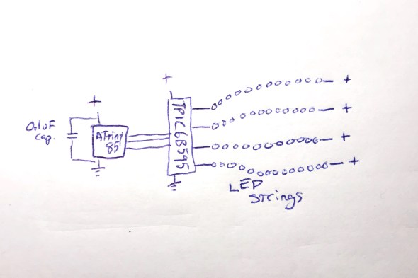
The small code size started me thinking: if I only need this tiny program, and this tiny amount of data, maybe instead of a full-blown Arduino board, I could just get away with a ‘bare’ ATtiny85 microcontroller. I knew that people did that, but I’d never done it. Luckily, there’s good documentation about how to wire up an ATtiny for programming, and good Arduino IDE support. https://github.com/SpenceKonde/ATTinyCore I decided to give this a try. I ordered a few ATtiny85s ($2.80 each) and the required (0.1uF) decoupling capacitors ($0.22 each). I used a special $15 ATtiny programmer to help simplify the programming process; I wanted to streamline the exploration of the ATtiny85 option as much as possible for myself.
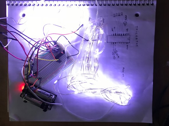
When the ATtiny85s arrived, it took me a little while to get it all figured out: burning the bootloader onto the chips, and then compiling and loading my code. My original code used the Arduino SPI library to communicate with the TPIC6B595, but the ATtiny85 doesn’t have a true SPI library, so I had to adapt my code (and my head) a little bit. Also, I had written an interrupt handler routine to provide PWM dimming of the LED strips, but my code had used the TimerOne library, which is not officially supported on the ATtiny85, so I had to find an ATtiny-patched version of the library and switch to use that. https://github.com/StoykoDimitrov/TimerOne Also, due to the slower clock speed (8MHz vs standard Arduino’s 16Mhz) I had to halve the interrupt rate that I was using for my PWM support. But eventually, I got it all breadboarded up and wired and programmed, and it worked!
Here’s where I was at that point: no Arduino board, no loose MOSFETs, no pull-down resistors, no current-limiting resistors:
Everything worked great, until it didn’t
Everything worked great, even when I switched from a plug-in power supply to battery power… and then it started not working. It would start up fine, and ‘rumble’ some dim lights with no trouble, and even show the first few medium-bright lightning strikes. But on the fourth lightning strike, an extra-bright set of flashes, it would lock up. It always locked up on the fourth flash, which was always extra-bright, because the random number generator that the code used to sequence the ‘random’ flashes was, in fact, completely deterministic. Even though it might not seem that way to the casual observer, the same pattern of flashes always occurred, and the fourth one was always extra-bright, and that kept killing the microcontroller.
Based on my previous experience with battery-powered microcontroller-driven projects with lots of LEDs, I had a hunch, which turned out to be right: when the LEDs all flashed on brightly, the drain on the batteries from the bright LEDs caused an inverse voltage spike – a voltage dip. The voltage dipped too low, just for an instant, and the microcontroller locked up.
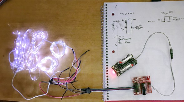
I thought about how I might isolate the microcontroller’s power from the sudden spike/dip from the LEDs flashing on full brightness. I could, of course, just reduce the maximum brightness of the LED strings, but this was a project for Burning Man, and I’m pretty sure that “reduce brightness” isn’t one of the ten principles. All I needed to do was power the microcontroller for a very short time, to bridge it across the dip caused by a very bright flash. I decided to try an experiment: I replaced the 0.1uF ‘decoupling’ capacitor ($0.22) next to the ATtiny85 with a capacitor with 10,000 times the power capacity: a 1000uF electrolytic capacitor ($1.22). My theory was that even when the LEDs spiked up in brightness, the new 1000uF capacitor would continue to provide just enough smooth power to the microcontroller it to keep running correctly. And it worked: even when bright flashes hit the LED strings, the microcontroller kept chugging along. Here’s where I was:
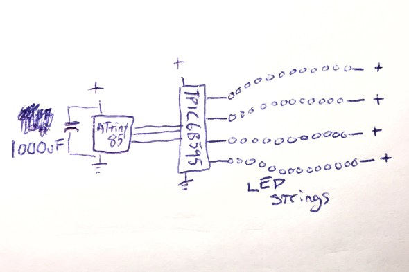
And this worked perfectly.
Now all I had to do was figure out how I was going to power this whole thing when it was mounted up inside an umbrella.
Hello Power My Old Friend
As I have written about before (see Cautionary Tales of Power), power is always a real pain in the grounding strap. Here were the choices that I was thinking about:
- 3xAA: this would be 4.5 volts on fresh batteries, and about 3.9 volts on ‘dead’ batteries. The microcontroller would probably work okay, and the LEDs would probably be okay, but I sort of felt like a 3xAA battery pack would be a little bit bulky and heavy. This was my ’emergency fallback’ plan.
- 4xAA: 6.0v on fresh batteries, 5.2v on ‘dead’ ones. I would have to use a voltage regulator, or a buck converter to drop the voltage down to the 4.5 – 5.0v range that I wanted. Plus a 4xAA battery pack would be even bulkier and heavier than the 3xAA pack above.
- Lithium Ion rechargeable battery pack: 3.7v when fully charged, 3.0v when empty. I’d probably want a boost converter to get up into the 4.5-5.0v range that I wanted. I love rechargeable batteries in general, but in the middle of the desert, there’s something to be said for being able to just eject a set of dead AAs, and drop in a fresh set. Using a lithium battery pack would make that much harder. Related options I thought about : standard 18650 cells, and also LiFePO4 cells.
- 2xAA + boost converter: this was what I really wanted to do. I wanted to use the DFRobot “AA Boost” module, which holds two AA batteries (very firmly), has a built-in on/off switch, and a boost converter which produces 5v output. It even has a “low battery” warning LED. The whole module costs $5.90 in quantity 1, and I’ve used them many times very successfully. https://www.dfrobot.com/product-991.html

I already had some of these 2xAA+boost modules on hand, and was about ready to go forward with this plan when I spotted this in the DFRobot description. Note the current limit on the updated “V2” version of this module:
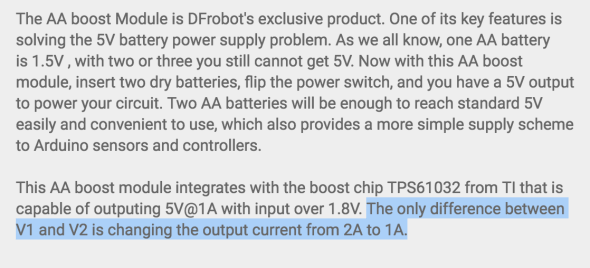
The maximum output current from this module was now just one amp. Not two, but one. One amp = 1000mA. And you may remember that the maximum power draw from the LED strings when they’re all fully lit, for a split second, is 1400mA total. And the 1400mA that we need is more than the maximum power that this module can provide.
Or… is it?
I looked up the TI TPS61032 boost chip that DFRobot uses in their boost module, and found the data sheet. http://www.ti.com/lit/ds/symlink/tps61032.pdf And while it definitely describes the chip as a “boost converter with 1000 mA current output”, look what it says in the highlighted (by me) portion of the datasheet:
And with that datasheet in hand, I decided to do the same thing that I’d done twice before on this project: try it, and see if the components can operate over and above their advertised ‘continuous’ ratings for brief periods, with cool-down rest periods between. And the answer? Yep, short bursts above the ‘continuous’ rating seemed to work fine!
I had had a battery-life goal for the umbrellas: I wanted them to be able to run, at Burning Man, from dusk to dawn (12 hours) on one set of AA batteries. Once I had the design all wired up with the DFRobot AA boost module, I popped in a fresh set of AAs, turned it on, and went to bed. Not only was it still running the next morning, it continued to run for over 48 hours continuously, and it might have run longer, but I had to get back to work on it, so I turned it off. Next I had to figure out what I was going to do about a circuit board.
The Chairman of the Board
I’ve never designed a custom printed circuit board before by myself, and I really wanted to do that for this project. Now that the total part count for each board was down to just three (the ATtiny85, the TPIC6B595, and the 1000uF capacitor!) it seemed like a great first project for me. However, time before Burning Man was getting a little tight, and I looked around for other options that might be faster and designing a custom board, and having it manufactured for me.
Over on Tindie, I found a great little ATtiny85 Project Board for $1.75. https://www.tindie.com/products/DrAzzy/attiny85-project-board/

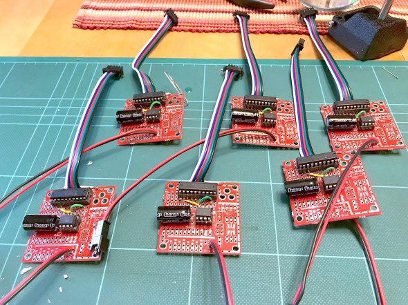
These little boards had: space for the ATtiny85, space for the 20-pin DIP TPIC6B595, and even a spot for the capacitor. I picked up some of these boards, added sockets for the DIP chips, seven jumper wires to inter-connect the two chips together correctly, attached some multiconductor connectors for the LED strings and power, and poof! Just look at that neat, tidy little red board there!
With all this ready to go, Sianna, Dean, and I worked out how we wanted the LED strings attached to the five-pin connectors. Sianna and Dean worked madly and mightily sewing the lights into the umbrellas, while I went into production mode, and made five more complete sets of boards and battery packs. If we’d been making more than six boards, I would have done a custom PCB for sure. Getting all those jumper wires right was my least favorite part of this project, but eventually it started going faster, and then they were all done!
To this day, I’m still pretty proud of the three-component controller boards, and the development path that got me here.
Putting it all together
Sianna and Dean did a tremendous amount of work sewing all the LED strings into six large white umbrellas. When the first one was all put together, it was time for the first visual test. Full disclosure here: the umbrellas do not make thunder noises; the thunder noises in the following two video clips were ‘added in post’. We had thought about what it would take to make really good thunder noises, and the short answer was: a really big power supply (read: a heavy battery) and a really big (read: heavy) speaker — neither of which was going to integrate well with a umbrella intended to be carried in one hand. So: no audio. You just have to imagine the thunder noises, or, in this case, you can listen to the ones I dubbed into the video.
So here was Stormbrella #1, sitting on the couch.
And then came the whole collection, Stormbrellas #1 through #6, scattered across the living room.
For reasons of time and technology, the six of them are not wirelessly synchronized with each other, but other than that, these were just what we hoped. Sianna and Dean took a bunch of them out to Burning Man, where the umbrellas flashed their lightning, and fought mightily with the high winds in the Black Rock desert. Some of the stormbrellas even lived to return home and tell the tale of their adventures, and their victory.
Epilogue: A Halloween Thunderstorm
For Halloween, the kiddo and I always liked to decorate the front yard of our house with a big theme, like turning the house into a castle, or a discotheque, or an aquarium. And that year, we made the front yard into a thunderstorm. We set up a big sound system to play thunder, programmed flash strobes to light up the front of the whole house, and all of the stormbrellas on stands, giving lightning and umbrella vibes at the same time. Also I put a sprinkler on top of the house so that it was actually raining the tiniest bit, completely with a baffle to keep the actual front walkway up to the house — and the trick-or-treaters — dry. The overall immersive effect was great, and the stormbrellas rode again!
I still have the stormbrellas, and sometimes when it’s a rainy night out, I carry one of them as I walk, happy and dry underneath as the lightning I made flashes overhead.
Making “Sun’mores” at 100ºF
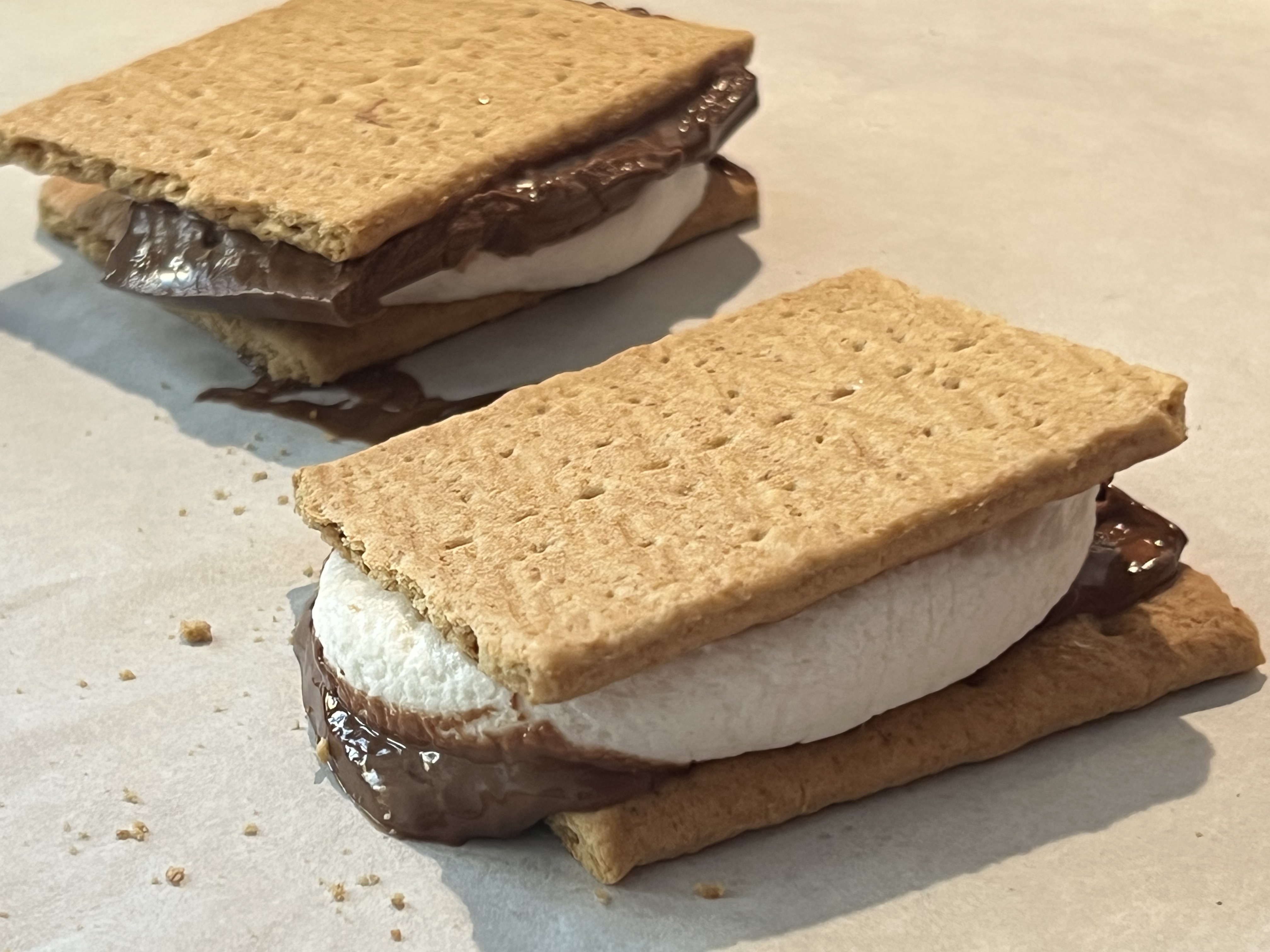
Posted: June 25, 2025 Filed under: Creations, Explorations, Food, How-to, That Totally Worked Leave a commentYesterday the temperature in Boston, at Logan Airport out by the water, hit a new record of 102ºF (39ºC). The temperature outside my window in Somerville was 105ºF (41ºC), and I said “It’s so hot that you could make s’mores by just stacking the ingredients outdoors.” Ness said “you should try it! it seems like a you thing to do”, and they were right and I bet you can already see where this is going.
I stacked some chocolate and some marshmallows on graham crackers, arranged it all on a baking sheet, and put it outside on my porch deck. It was 3:46PM, and the sun was already well past its highest point, but the air itself was scorching and the chocolate started melting immediately.


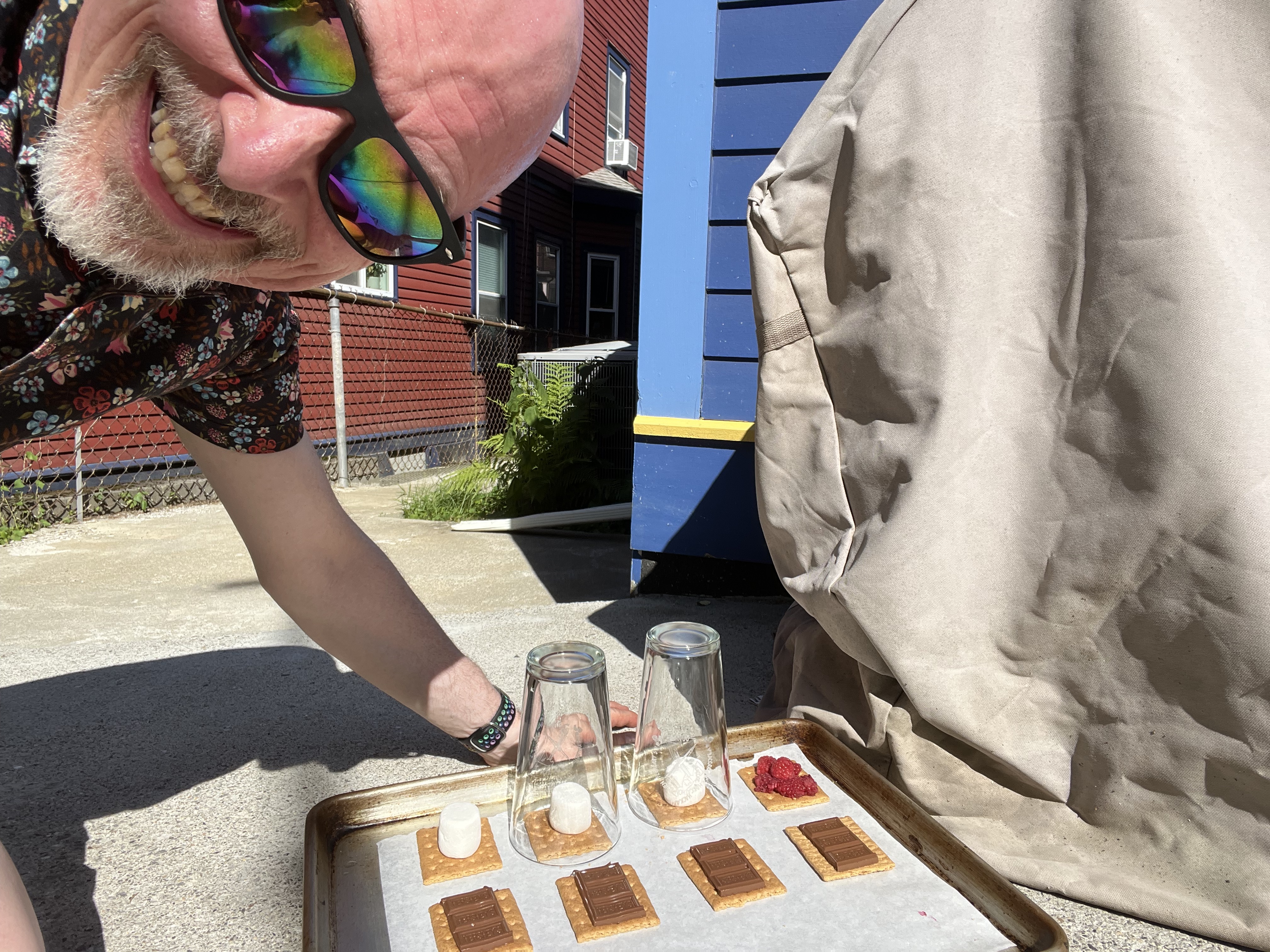
I had to move the tray from the front of the house to the back to keep it in direct sunlight. At the same time, I decided to try an experiment: putting a glass ‘greenhouse’ dome over some of the marshmallows to see if it helped them melt. For that I used pint glasses, which coincidentally (I presume) are almost exactly the right size for a standard graham cracker.
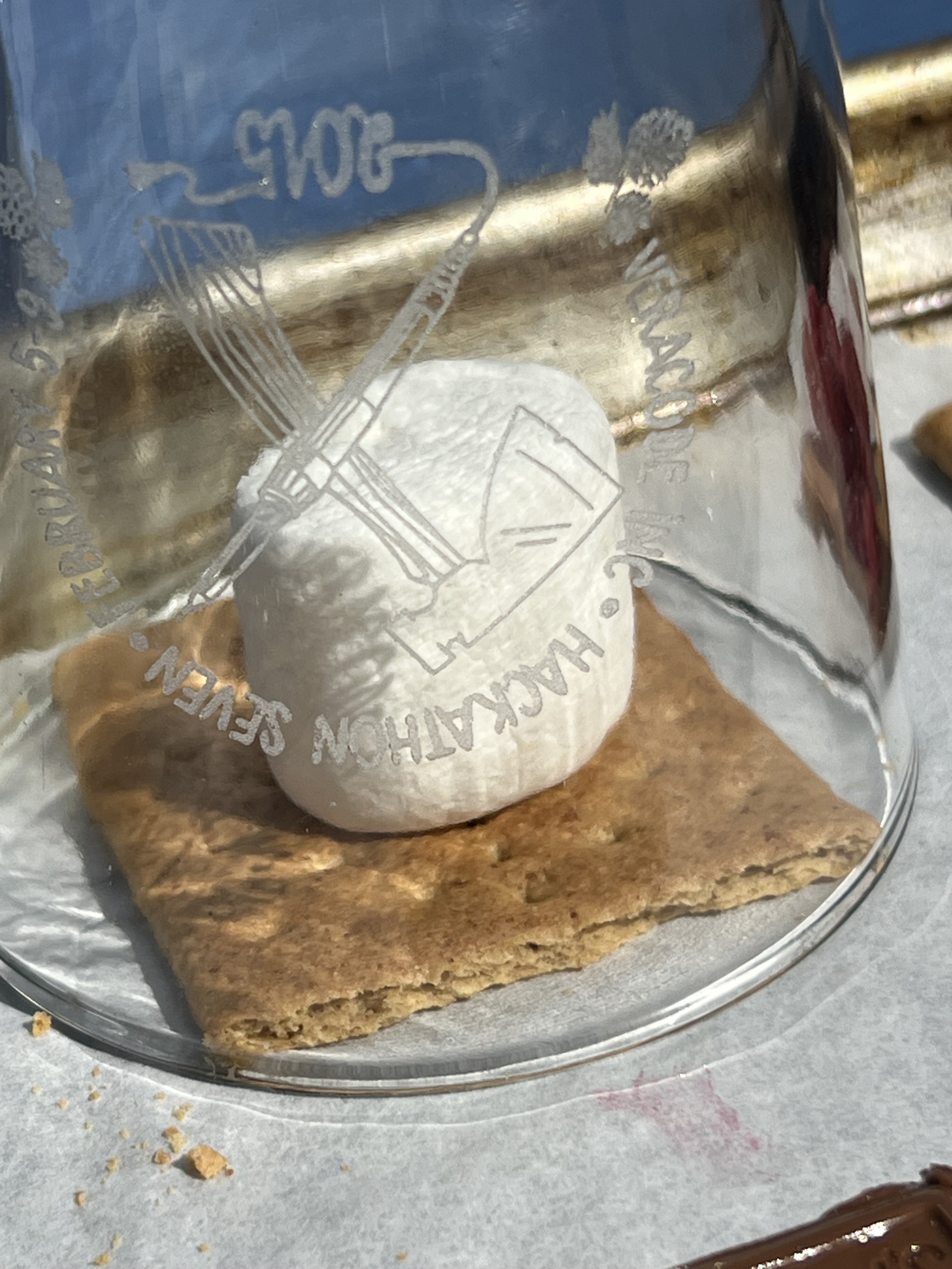
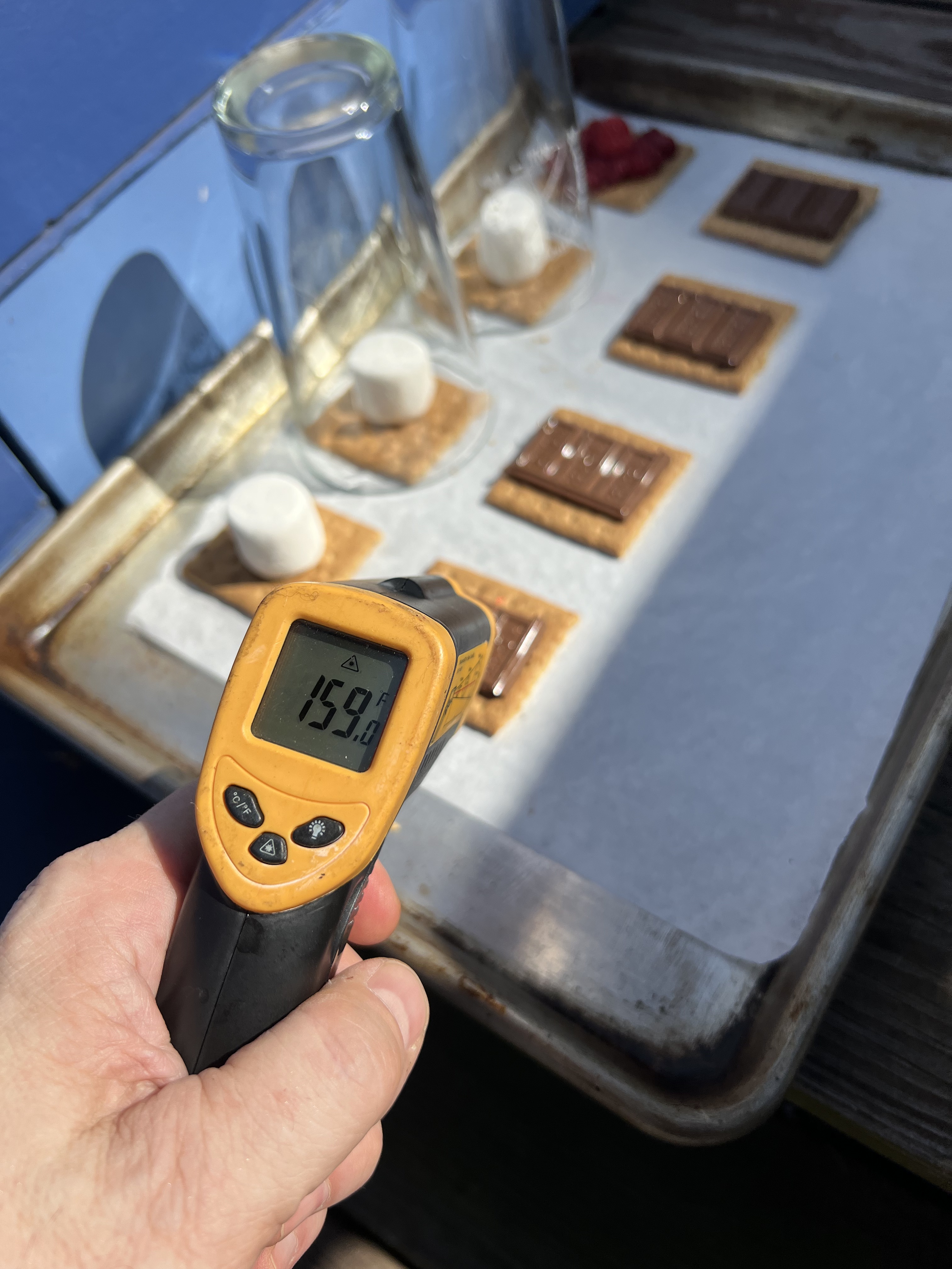
Now things were really heating up. The air temperature was 104ºF (41ºC), but the chocolate’s dark surface had allowed it to absorb more of the sun’s energy, and I measured its temperature as 159ºF (71ºC)!
In addition to the traditional graham+chocolate+marshmallow combination, Molly set up a fruit combination: graham+chocolate+raspberries, which you can also see in the first photo above.
The ingredients had now been outside for just exactly one hour, the sun was starting to get lower in the sky, and even though I was only running outside for quick checks on the ingredients, I was getting overheated and it was time to move on.
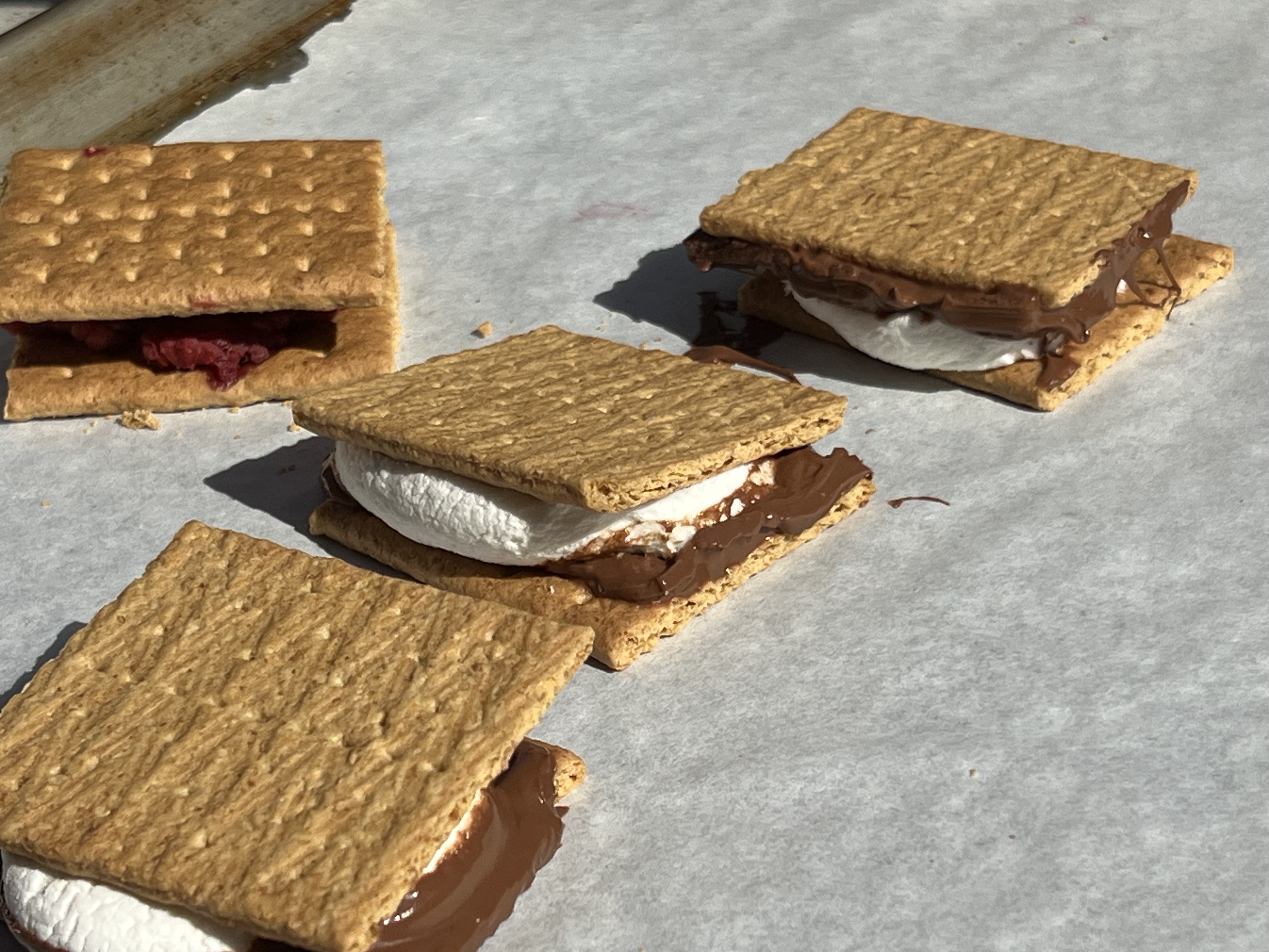
Time to assemble the final product! But: would the chocolate really be entirely melty? Would the marshmallows really be gooey all the way through? And would the greenhouses have made any difference? It was time to find out.
Although the marshmallows hadn’t deformed just sitting there, they were really quite gooey, and the greenhoused marshmallows were, in fact, even softer and gooier! Assembling the final sandwiches was easy, and everything melted and mixed and blended, just like campfire s‘mores.


I bought the (very hot!) baking sheet indoors, where Molly, Sarah, I, and a couple of area teens did some long-awaited taste-testing. It worked! We had tested my hypothesis that you could make s’mores just by putting the ingredients outdoors on a 100ºF day, and found that you can, and should! If we had started closer to solar noon, and if we’d put a greenhouse over all the ingredients (perhaps a glass 9×13 baking pan, upside down?) I think they would have gone much faster, perhaps in 20-30 minutes.
The fruit combination, raspberry+chocolate+graham was particularly delicious, and felt extra summery. Molly suggested next time doing fruit+cheese, and Sarah joined in to say that if we did that next time, that we should put it on something better than a graham cracker.
After some back and forth, we officially named these “sun‘mores“, and decreed that they can only truly be created on days when the temperature hits 100ºF, which it certainly did yesterday!
And when Ness saw all this they exclaimed simply, ”by jove!!!”

Giving the Gift of Receiving
Posted: June 29, 2020 Filed under: Art, Getting A Clue, Pearls of Folksy Wisdom, Reflections, That Totally Worked | Tags: burning man, gift economy, gifting, gifts, giving, pineapple Leave a commentWhen you’re a little kid, the proverb “It is better to give than to receive” sounds like nonsense grown-up talk; most little kids would rather get a toy than give one away. But here’s a story about giving and receiving that shows what the proverb is really trying to express.
In 2010, I went to Burning Man with a bunch of friends. My friend Debby and I were walking around the city there, checking out all the art projects, and Saturday afternoon, after we’d all been living in the desert for a week, we came across a Wishing Well.

Here’s how the Wishing Well worked: you could make a wish, or you could grant a wish. To make a wish, write your wish on a rock (provided), along with your name and where you were camping. To grant a wish, rummage around through the stones that other people had written their wishes on, and see if there are any wishes you can grant. If so, take the stone with you, go find the person who wished on it, and make their wish come true.
I decided to make a wish. I wrote on a stone that I wished for a trinket to bring home to my daughter. I added my name, camp location, and tossed it in the Wishing Well.
While I was doing this, my friend Debby was rummaging around in the wishes that other people had tossed in the well. She held up a few stones that said all sorts of predictable things, and then held up a stone that said that “Dave” at such-and-such a camp was wishing for “fresh pineapple”. The entire population of the city had been camping in the desert for a week, and fresh fruit was an exotic wish indeed. But then Debby said, “I’ve got one.”
“You’ve got one what? A pineapple?”, I asked laughingly.
“Yes. A whole fresh pineapple. I have one. It’s been packed in ice all week, in a cooler, back at our camp.”
I was incredulous. “What were you going to do with your pineapple? Do you have a plan for it??”
“No”, she said, “I didn’t have a plan. It just seemed like a good thing to have.”
“Well, do you think we should bring it to ‘Dave’, and grant his wish?!?”
“Definitely,” Debby said.

So we took Dave’s wishing stone, went back to our camp, dug the whole, entire fresh pineapple out from the cooler, and set off to find Dave. Black Rock City (Burning Man) is never really entirely organized. In 2010, the population was over 50,000 people, and even though we had an approximate address of where to find ‘Dave’, Debby and I had to wander around quite a bit, and ask a lot of people for directions and clues before we triangulated on Dave’s camp.
When we found the right camp, we started asking “Does anyone here know Dave? Is Dave here?” After a few minutes, Dave poked his head out of a tent and said “Who are you? Why are you looking for me?”
We said, “We’re here from the Wishing Well. Are you the person who wished for fresh pineapple?”
“Yes? Yes…” he said starting to choke up, disbelieving, and getting emotional. “Yes, I did wish for that, but I thought it was impossible… oh my god…”
We handed the fresh pineapple, still cool from the ice, to Dave, who took it. He stared at it as if it weren’t real, as if none of this was really even happening. He broke out in tears of joy, hugging first the pineapple, then us, then the pineapple again. Debby and I told him to enjoy it, and we went on our way, grinning and laughing.
The next day, someone I didn’t know stopped by our camp, asking “Is Mark here? Does anyone know Mark?” I said “I’m Mark”, and they handed me a little hand-made necklace with the Burning Man logo on it, and said “This is for you to bring home to your daughter; I found your wish in the wishing well. I made this necklace, and I want you to bring it to her!” I gave a big smile and a big thank you, and a hug, and tucked the necklace away somewhere safe for my trip home.
Later, I was reflecting on these two experiences: receiving the thing that I had wished for, and giving someone else what they had wished for. It was exceedingly clear to me which had been more rewarding to me. While I did like receiving the necklace to bring home, granting Dave’s wish for pineapple had made me feel absolutely wonderful inside, and that feeling still stays with me today. So, I thought, I guess it really is better to give than to receive.
The more I thought about it, the more I came to realize that the real gift had been the one that Dave gave to me and Debby: by asking for something, Dave had given us the chance to give it to him, and then to feel wonderful about it. It’s the same gift that I gave the necklace artist by asking for a trinket to take home: a chance to do something nice for someone and feel wonderful about it.
I think about this story when people offer “Is there anything I can do to help? Is there anything I can bring you?” My first impulse is often to say “No thank you, I’m all set”, because I don’t want to impose on them. But then I think that maybe a better answer is to say “Why yes, actually, there is one small thing that would be nice…”, because then I am giving them the gift of being able to do something nice for someone, and to feel good about it. It’s “giving the gift of receiving”.
Sometimes, by asking for something, we can make other people happier, and that seems worth doing. Someone’s got to toss their wishes into the well, so other people can grant them.

Harbinger of… autocomplete
Posted: June 2, 2018 Filed under: Explorations | Tags: words Leave a commentAccording to Merriam-Webster, a harbinger is “something that foreshadows a future event, something that gives an anticipatory sign of what is to come.”
So, now what’s the first phrase that comes to mind if I say “harbinger of _____” ?
Based on a casual poll, it seems that a majority of people answer with something like “harbinger of doom!”, a dark portent to be sure. But, on the other hand, there’s also a substantial minority of people who seem reply with “harbinger of spring!”, a far more cheerful spirit.
This got me thinking. What other harbingers of X are there out there, and are they more positive (like spring) or negative (like doom)? Well, Google autocomplete to the rescue! I went to Google twenty six times, and each time typed in “harbinger of” followed by a letter of the alphabet, and I let Google autocomplete whatever it wanted to, like this:

Here’s the table. In some cases, Google autocomplete didn’t give one clear answer, and so I left that line blank with a [?] note.
| Harbinger of… | Bad | ? | Good | ||
| A | Apocalypse | 1 | |||
| B | Blood soaked rainbows | 1 | |||
| C | Change | 1 | |||
| D | Doom | 1 | |||
| E | Evil | 1 | |||
| F | Flame | 1 | |||
| G | Good things to come | 1 | |||
| H | Hope (#2: haggis) | 1 | |||
| I | Impending doom | 1 | |||
| J | Justice (#2: joy) | 1 | |||
| K | Knowledge | 1 | |||
| L | Light | 1 | |||
| M | Madness | 1 | |||
| N | Night | 1 | |||
| O | O [?] | ||||
| P | Peace (#2: pestilence) | 1 | |||
| Q | Q [?] | ||||
| R | Ragnarok | 1 | |||
| S | Spring | 1 | |||
| T | Things to come | 1 | |||
| U | U [?] | ||||
| V | Vengeance | 1 | |||
| W | Winter | 1 | |||
| X | X [?] | ||||
| Y | Your perfection | 1 | |||
| Z | Z [?] | ||||
| TOTAL | 8 | 5 | 8 | ||
| Bad | ? | Good | |||
A side note: that whole “harbinger of blood-soaked rainbows” business? That comes from this bit of awesomeness: https://shop.theoatmeal.com/products/the-mantis-shrimp-is-the-harbinger-of-blood-soaked-rainbows-signed-print
So there you have it. If you take Google autocomplete as an accurate representation of totality of human spirit, intention, and our vision for the future, then there is currently an epic, but balanced, struggle between good and evil in our vision of what is yet to come.
That may be true right now, but that doesn’t mean we’re powerless to change it. If you personally choose to use “harbinger of spring” more often than “harbinger of doom”, you’re tipping the scales of the future toward the light, and that seems like a harbinger of peace.
82°
Posted: June 1, 2018 Filed under: Art, Coding, Creations, Explorations, How-to, That Totally Worked Leave a commentThis is a 100% recycled yak fur story.
Molly asked me a thoughtful question while I was in the middle of something else and I said “Just a second, I need to rotate my brain.” A moment later, I said OK and she asked me if my brain was all rotated now. I replied, “Well, 82° out of 90°, close enough.” Molly quipped “And since when did you ever do things square?”
But then I nerdsniped myself. I started to wonder about 82° angles. If a polygon with 90° angles is a square, what sort of polygon do you get if you turn 82° at each corner? It’s not one of your basic shapes, because:
- 120° angles make a triangle (3 sides, since 360° ÷ 120° = exactly 3)
- 90º angles make a square (4 sides; 360° ÷ 90° = exactly 4)
- 82° angles make a ??? (?? sides; 360° ÷ 82° = 4.3902439024???)
- 72° angles make a pentagon (5 sides; 360° ÷ 72° = exactly 5)
It must be some kind of … star shape, 82 doesn’t go evenly into 360, which means that you’d have to spirograph-around the circle more than once to come back to where you started.
But what kind of star? How many points would there be on a star with 82° angles at each point? I decided that I had to know, and that I wanted to see what the star looked like, not just find out the numeric answer. The numeric answer is the GCD of 82 and 360, and I could figure that out, but then where’s my picture of the star? I decided to write a quick program to draw stars with angles of ‘N’ degrees at each corner, and to print out how many points there were on the star.
And what’s a quick way to write a program to draw connected lines at various angles? With Logo and turtle graphics, naturally. Luckily, I’ve already done some programming in Logo. Unluckily, it was back in the 1980s. But it’s like riding an (imaginary) bicycle, right? I was sure I could remember and pick it up again quickly. I also (correctly) guessed that there were probably Logo interpreters that ran in a web browser using Javascript. I chose this one, because it had handy examples and Logo language reference documentation built in: http://www.calormen.com/jslogo/
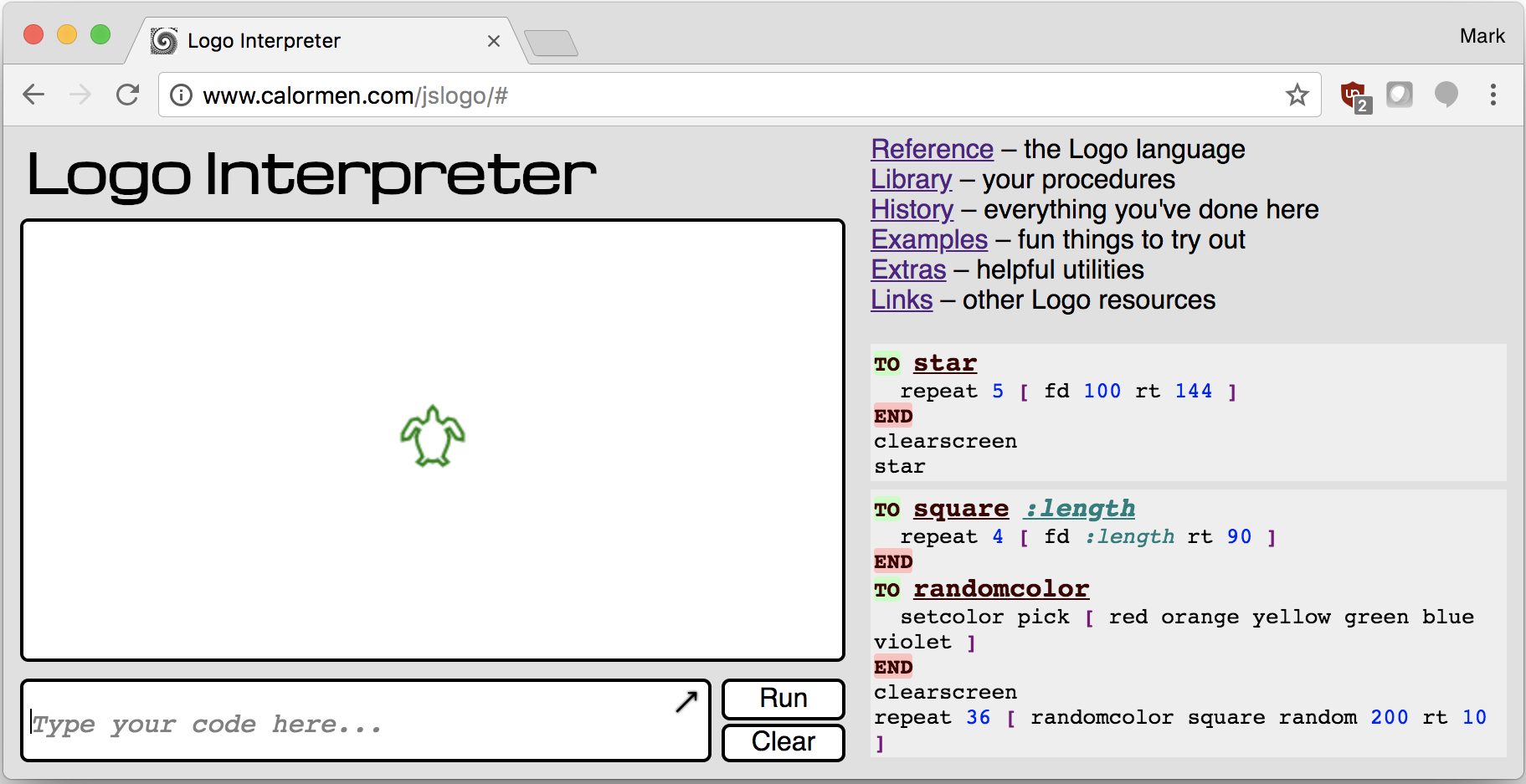
So ten minutes later, I had refreshed my Logo skills. Luckily, Logo is secretly sort of a dialect of LISP, and I’m very comfortable with LISP-like languages. Here’s the code I finally came up with:
to anglestar :angle
  clearscreen
  penup
  forward 150
  pendown

  make "count 1
  setheading :angle

  while (heading > 0) [
    forward 200
    right :angle
    setheading round modulo heading 360
    make "count sum :count 1
  ]
  forward 200
  show :count
end

anglestar 82
Now experienced, professional Logo authors will notice that there’s a ’round’ in there. Why is that? If all these numbers are integers, why do I need to ’round’ the numbers at all? Well, I didn’t have it in there at first, and the program wasn’t stopping. At all. It’s because this particular implementation of Logo, in Javascript, uses Javascript floating point numbers for Logo numbers, and since “modulo” is a floating point division-remainder operation in Javascript, sometimes instead of coming back with an answer like 377 modulo 360 = 17, it was really doing something like 377.0 modulo 360.0, and coming back with an answer like 17.000001, because floating point math is way more complicated and hard that you might think. So after having this problem, and fixing it by inserting a ’round’ into the heading math, everything worked better. Here’s the output from N=82°
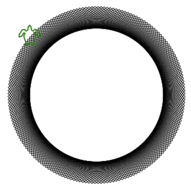
And it printed “180”, meaning that this is a 180-point star. Or, as Molly pointed out, more of a bike wheel than a star really. An imaginary bike wheel.
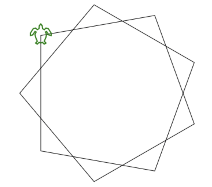
I decided to try other angles since I now had this great program. With N=80°, you get a nine-pointed star, because 80° x 9 = 720°, which is twice around the 360° circle:
And with N=81° you get a 40-pointed star:
Although as Molly pointed out, this one isn’t really a ‘star’, either. This one is more of an imaginary bicycle gear, a lot like this real 40-toothed bicycle gear:

So anyway, the answer to the original question, “How many points are there on a ‘star’ whose lines meet at 82° angles?” is …. 180. (And yes, the GCD of 82 and 360 is, in fact, 180!) But to figure it out my way, I had to refresh my 35-year-stale Logo skills, debug and code around a Javascript floating point math issue, and now the floor is totally, completely covered in yak fur.
Oh, and after all this, Molly very patiently re-asked me her original question again, and I answered her without yak-further delay.
Easter Egg Hunt 2017
Posted: April 17, 2017 Filed under: Creations, DIY, Explorations, Getting A Clue, That Totally Worked, Uncategorized | Tags: chocolate, colors, Easter, easter egg hunt, easter eggs, fonts, logic, puzzle, puzzle hunt, puzzles 2 CommentsOh, we love our Easter Egg hunts.
Oh, we love our Easter Egg hunts. As the girls (now age 14) have grown from little kids, to tweens, to actual teenagers, what started as a simple find-the-hidden-eggs game has grown right along side them; it’s now a full-on multi-stage puzzle hunt. 2014’s hunt involved complex interlocking rules. 2016’s hunt involved cryptography and QR codes. Now, here’s how 2017’s puzzle unfolded…
Simple
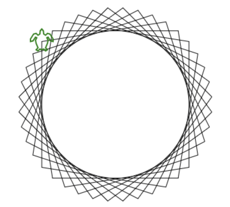
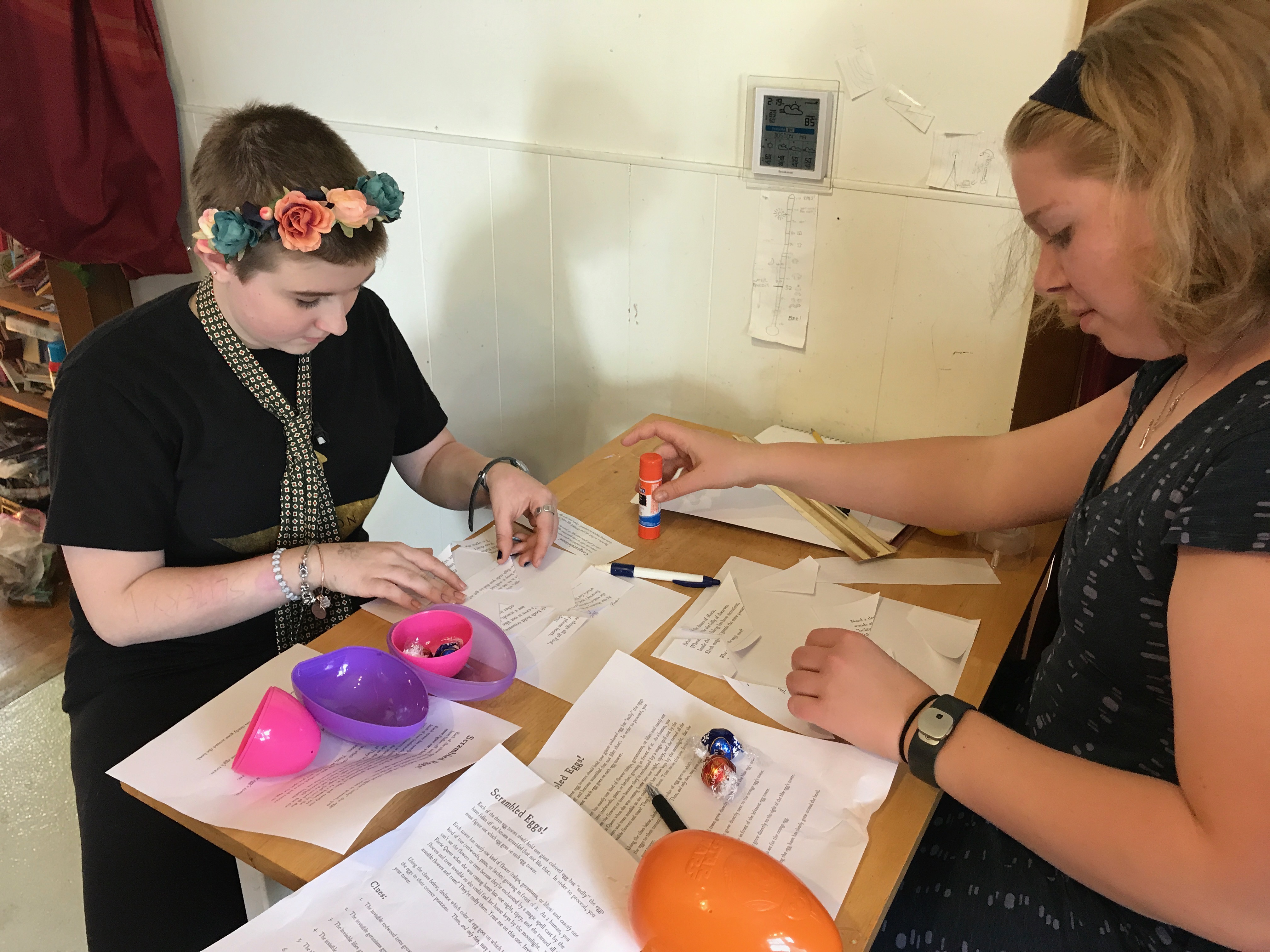
The rules were simple: each girl would be assigned a couple of colors, and each girl could pick up any egg she found once she was certain that the egg matched one of her colors. Easy, right? Further ‘simplifying’ things, I announced that I had placed one giant colored egg on a pedestal with each girl’s name (and one for the parents), so all they had to do was look at the pedestal with their name, and they’d see their first egg color. I showed them all a picture (below) of how nicely I had set it up, and how easy it was going to be.

But when we got outside to start collecting eggs… quelle surprise! The wind seemed to have blown the eggs off their pedestals! How ever would the girls know which color was theirs??

Luckily, each pedestal contained a set of instructions for figuring things out in case of just such an emergency:
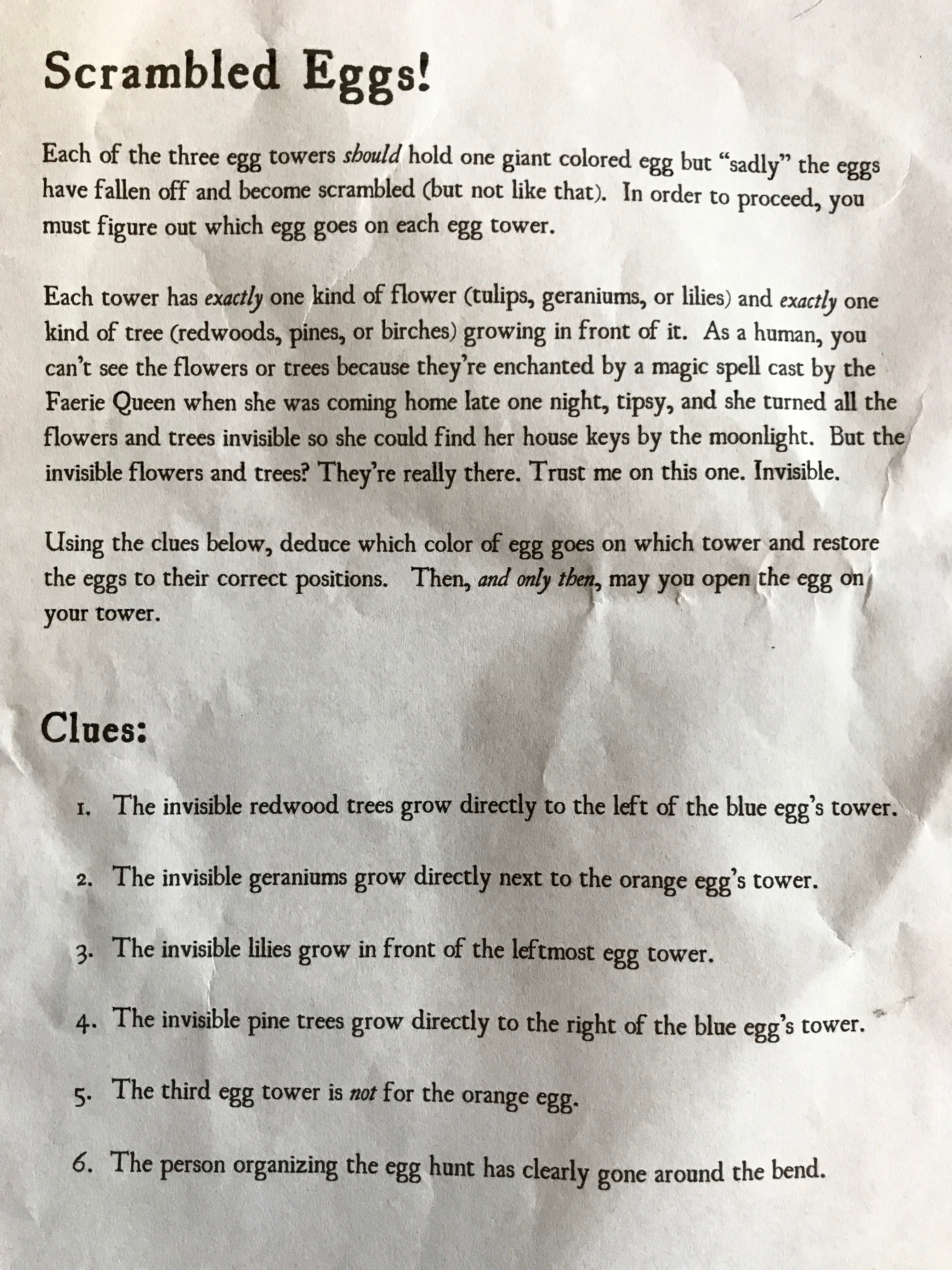
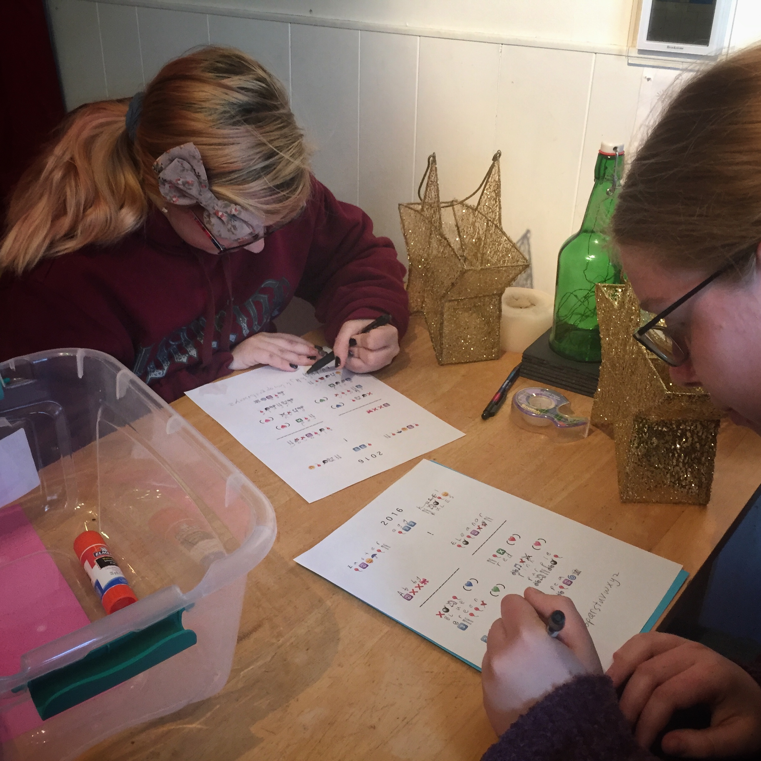
The girls retreated to the kitchen to pencil-and-paper this problem. After a few minutes, they’d worked it out with Rebecca offering supportive coaching (but not giving away the answers even though she’s great at these puzzles). The girls hastened outside to each crack open their correct-color giant eggs.

Inside each giant egg was a message… and another, smaller egg.

Inside the smaller eggs was some chocolate, which was immediate consumed as much-needed brain fuel. And there were also some scraps of cut up paper with writing across them — clearly they needed to be reassembled. The girls hurried back inside, and taped the paper back together, revealing four trivia questions about opening magical doors. (Full credit here: Three of these riddles were written by Ryan O’Boyle for Veracode Hackathon 10 & 5/7ths. His riddles were great, and inspired me to add one additional one of my own.)
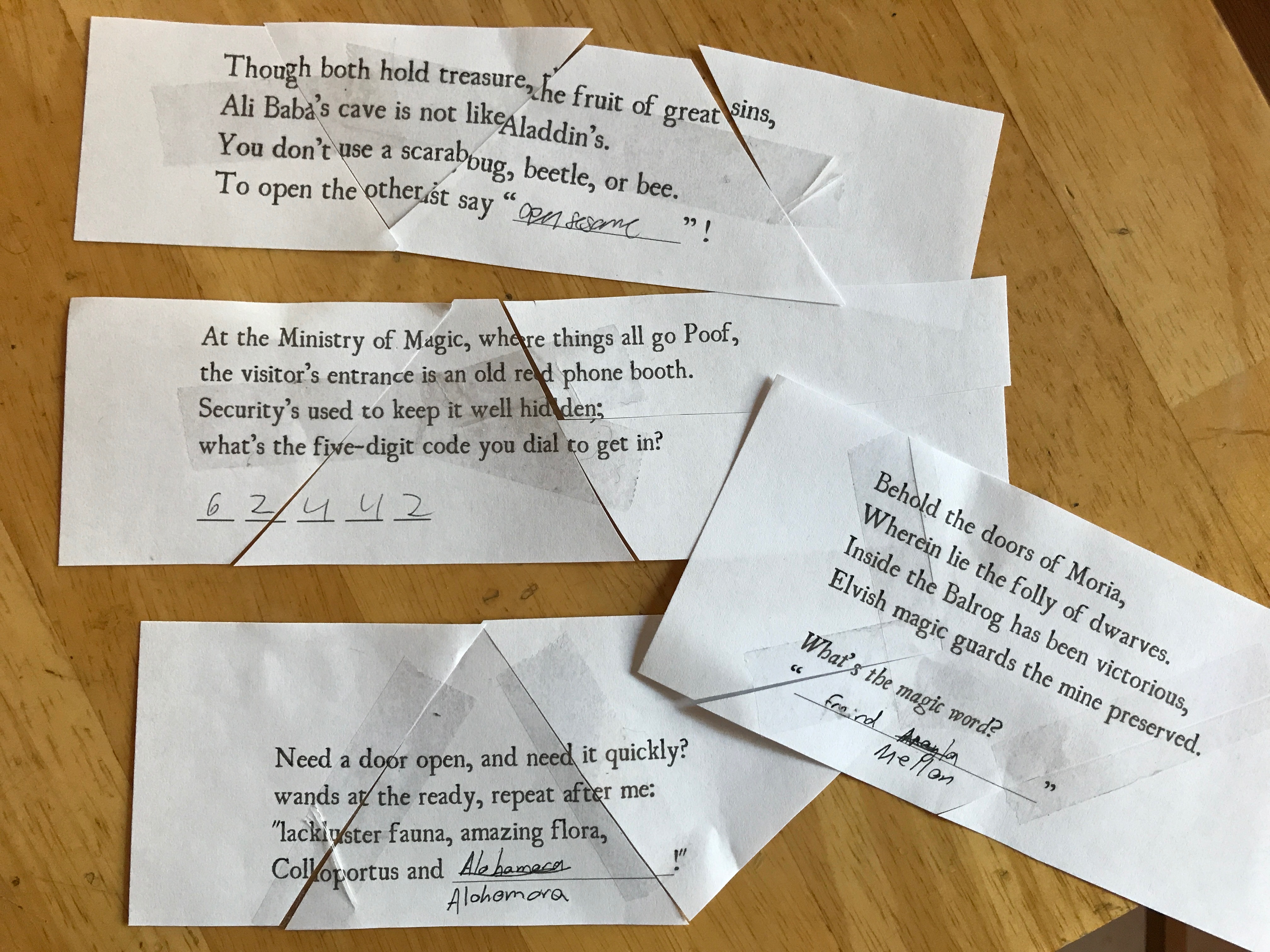
It just so happened that the team included a Tolkien expert (Norm), and several Harry Potter fans (everyone but me) so the answers were quickly found. Bonus points to Abby for remember the spell “Alohomora”, and to Eleanor for remembering that the Ministry of Magic’s phone booth code was “M A G I C” on the telephone dial — and then using the Phone app on her iPhone to look up what numbers that was.
But now what? The girls still needed to know what colors of eggs they each were looking for, and all they had were these trivia answers — definitely not colors. Well luckily the third giant egg, the one for the parents, contained a “Helpful, Quick, and Easy Egg Color Key!” with some hand-wavey formula clues on it about how to transform the trivia question answers into numbers.
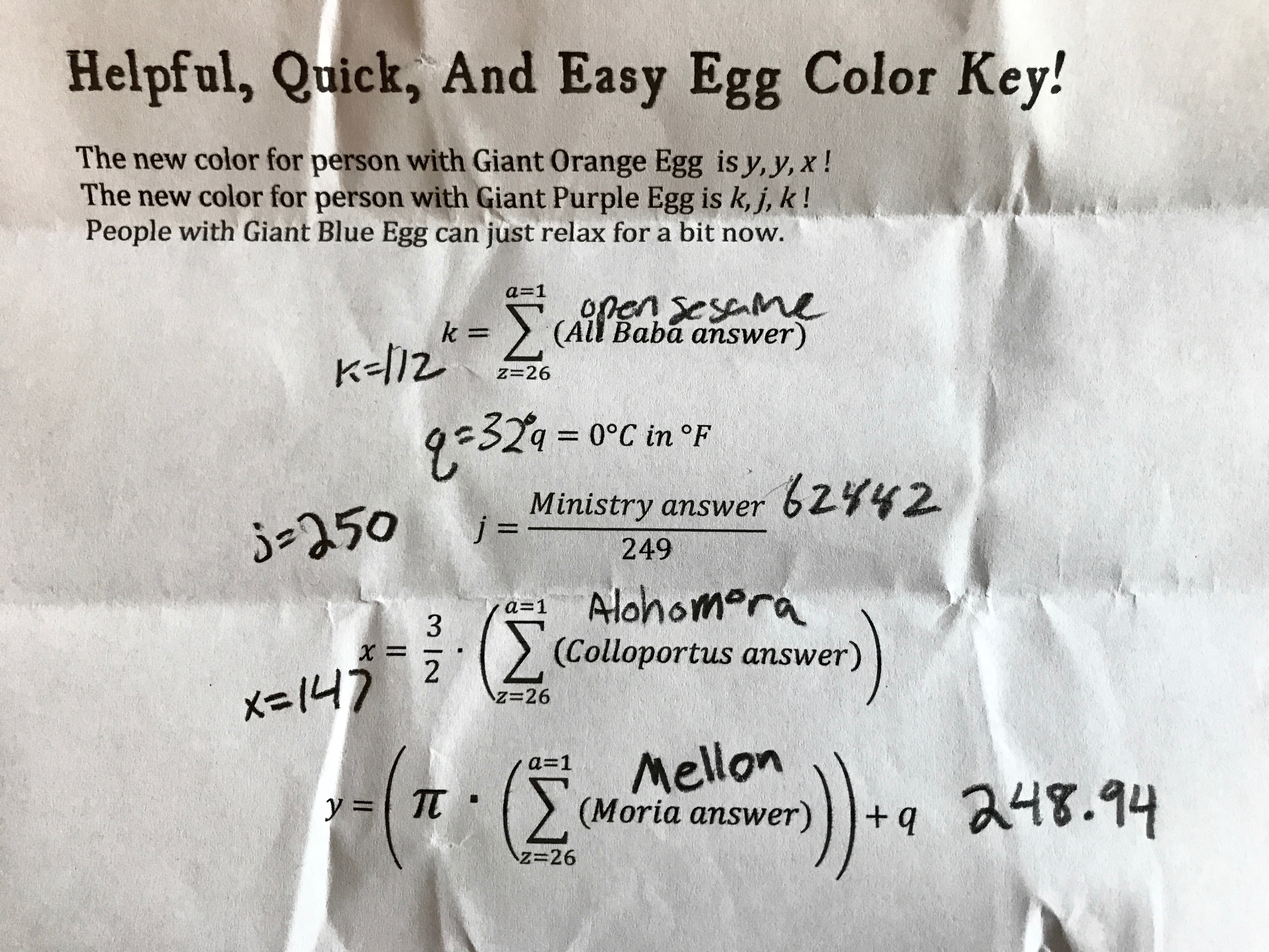
By considering a=1, b=2, etc., and adding up the letters in each trivial answer (and after I fixed a typo..oops), the girls arrived at numeric values… but still no colors. It was more or less at this point that Eleanor started invoking the word “patricide” in her running commentary.
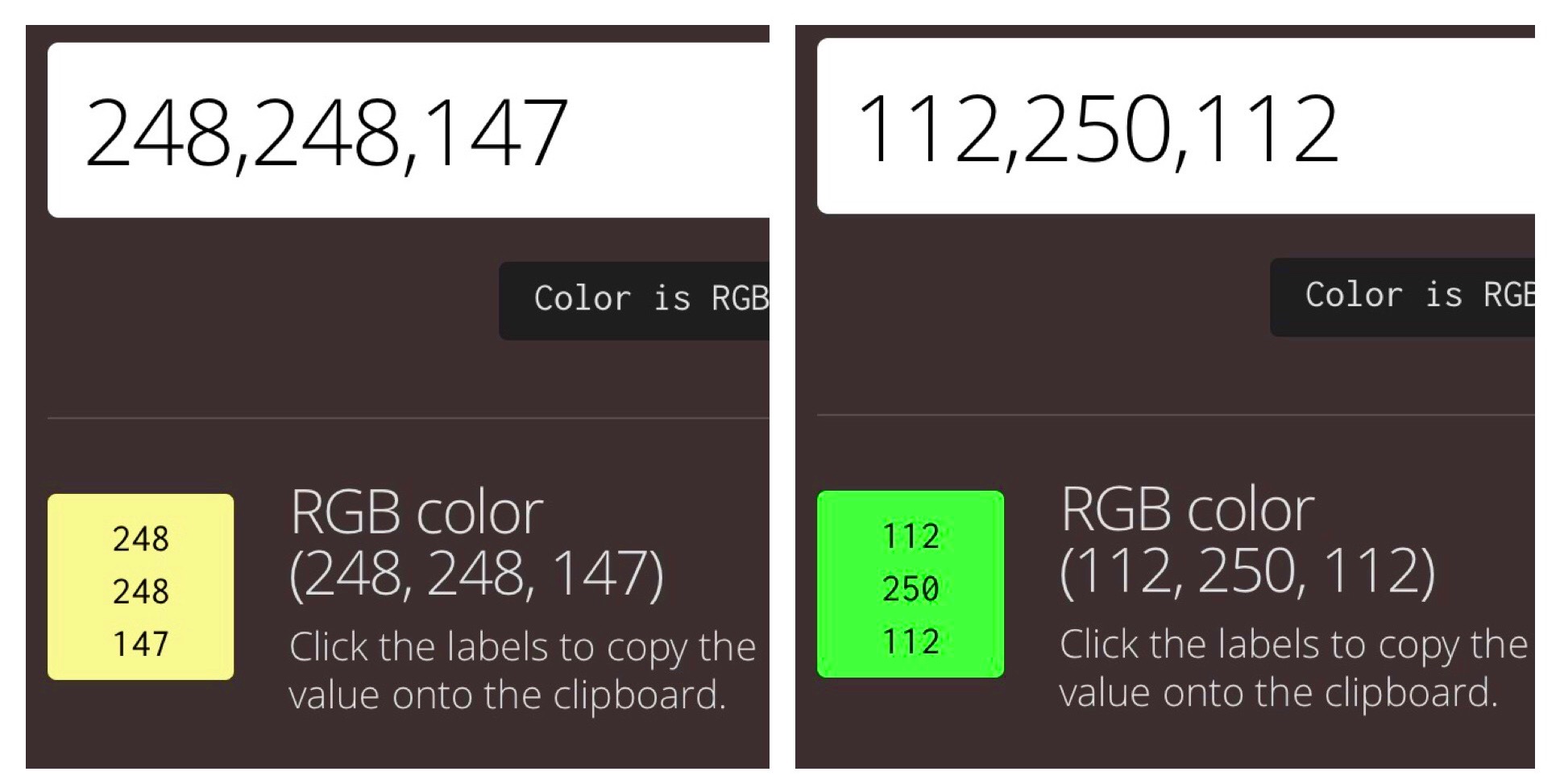
Working through the formulas provided on the key, the girls had figured out that the variables k=112, j=250, x=147, and y=248, so, again, they had some numbers, but no colors. The key said that one color was y,y,x and the other color was k,j,k.
“But how are those colors?”, Rebecca asked, and there was a moment of silence.
“HEX CODES!” Eleanor exclaimed, and the chase was back on! Using an Internet color code converter, the girls converted 248,248,147 into yellow, and 112,250,112 into green. Colors at last!
Now with each of the girls knowing exactly which egg colors were theirs, they scooted out to the yard. Within just a few minutes, they’d found all of the (poorly) hidden eggs, collected them, and returned to the kitchen inside to savor the chocolate goodies within.
Then came the screams.
Then came the screams. For inside each egg not only was there a tasty bit of chocolate, but also… more sliced up message fragments. There was clearly another part of the puzzle. Madly, the girls sorted out all the pieces and assembled them:
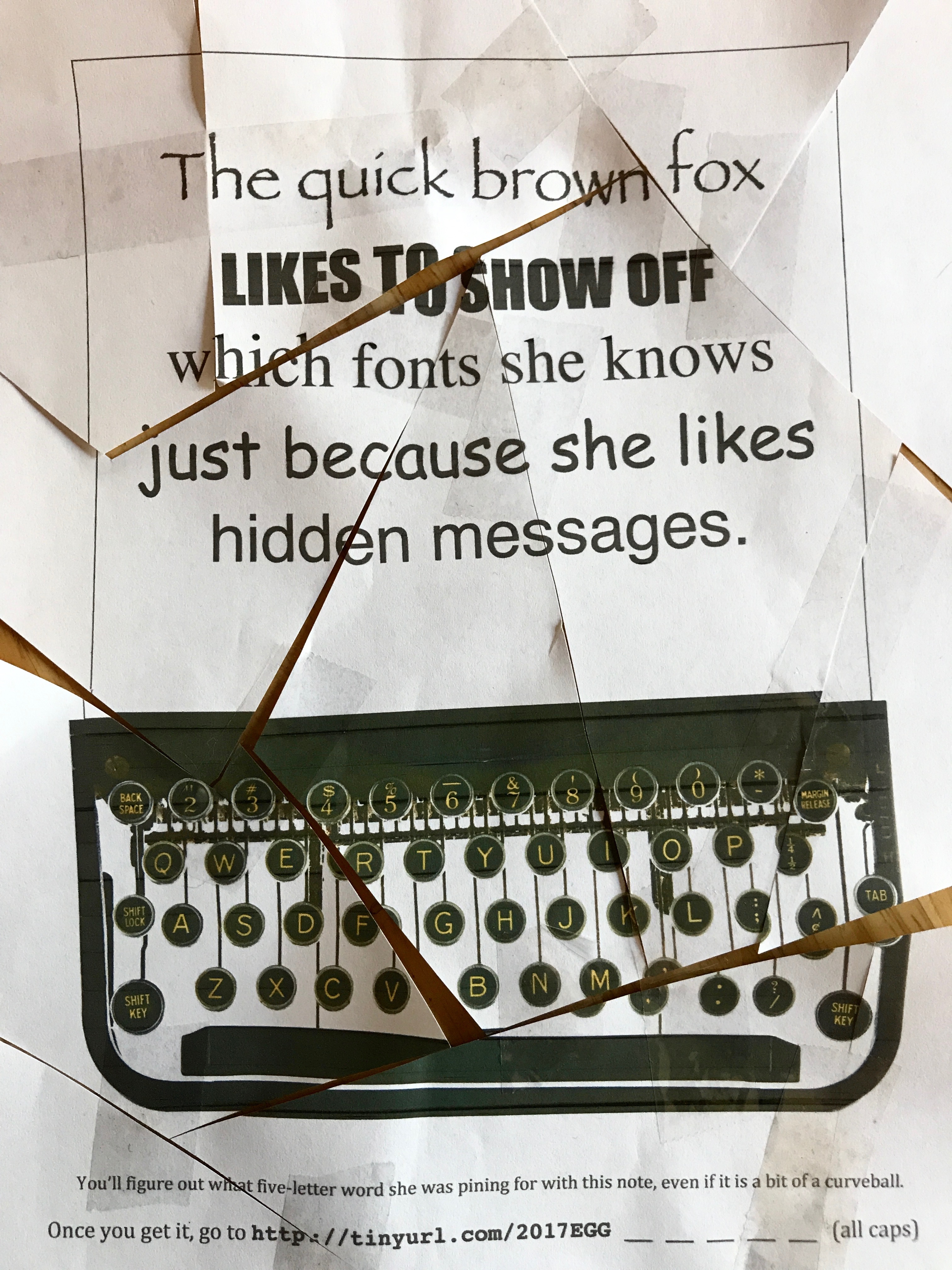
The team stared at this for a while, and then started discussing the fonts: Papyrus, then a font that no one knew the name of, then Times, Comic Sans, and Helvetica (with a quick argument about Arial… ending with “Well, young lady, in this house, we use Helvetica!”). Could the five-letter word that the clue was asking for be made from the initials of the fonts? P_TCH? PATCH was considered for a minute, but when the girls hit on PITCH, the hints about “pining”, “note”, and “curveball” all clicked!
Using PITCH, they completed the partial URL and typed in http://tinyurl.com/2017EGGPITCH What came up at that URL was a photograph of the front of the house, with a big green arrow.

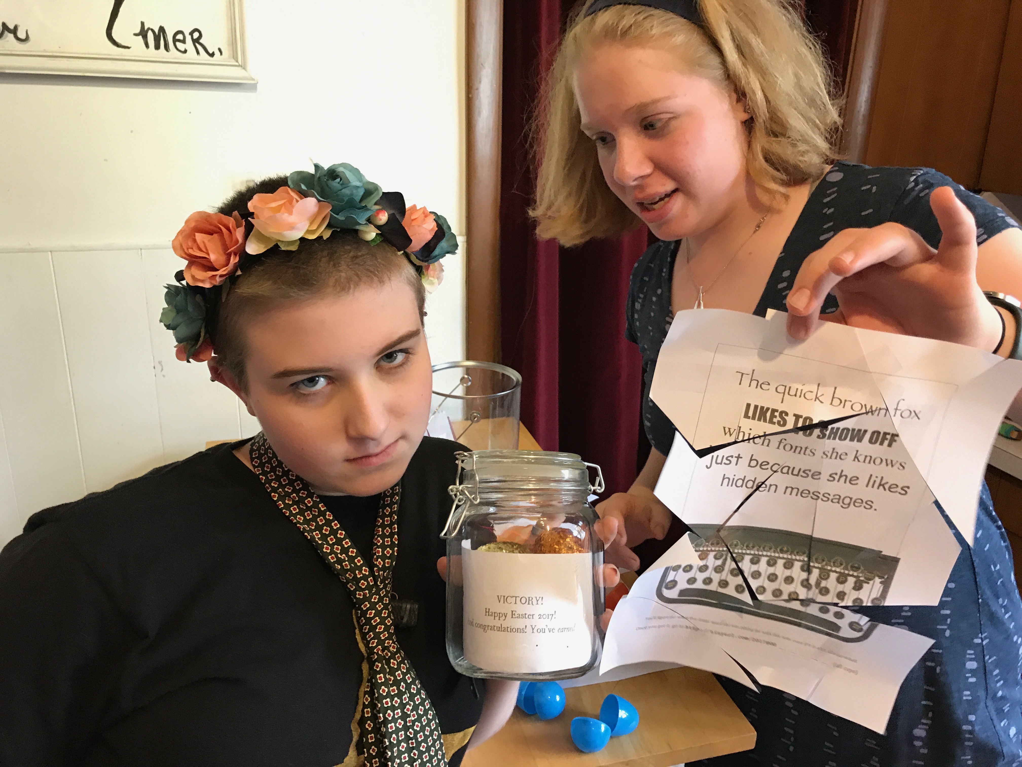
The girls practically flew out the front door, flipped over the flowerpot in the picture, and were rewarded with a glass jar filled with glittery treasure eggs, yet more chocolate, and a note saying VICTORY! CONGRATULATIONS on SOLVING the 2017 Easter Egg Hunt!
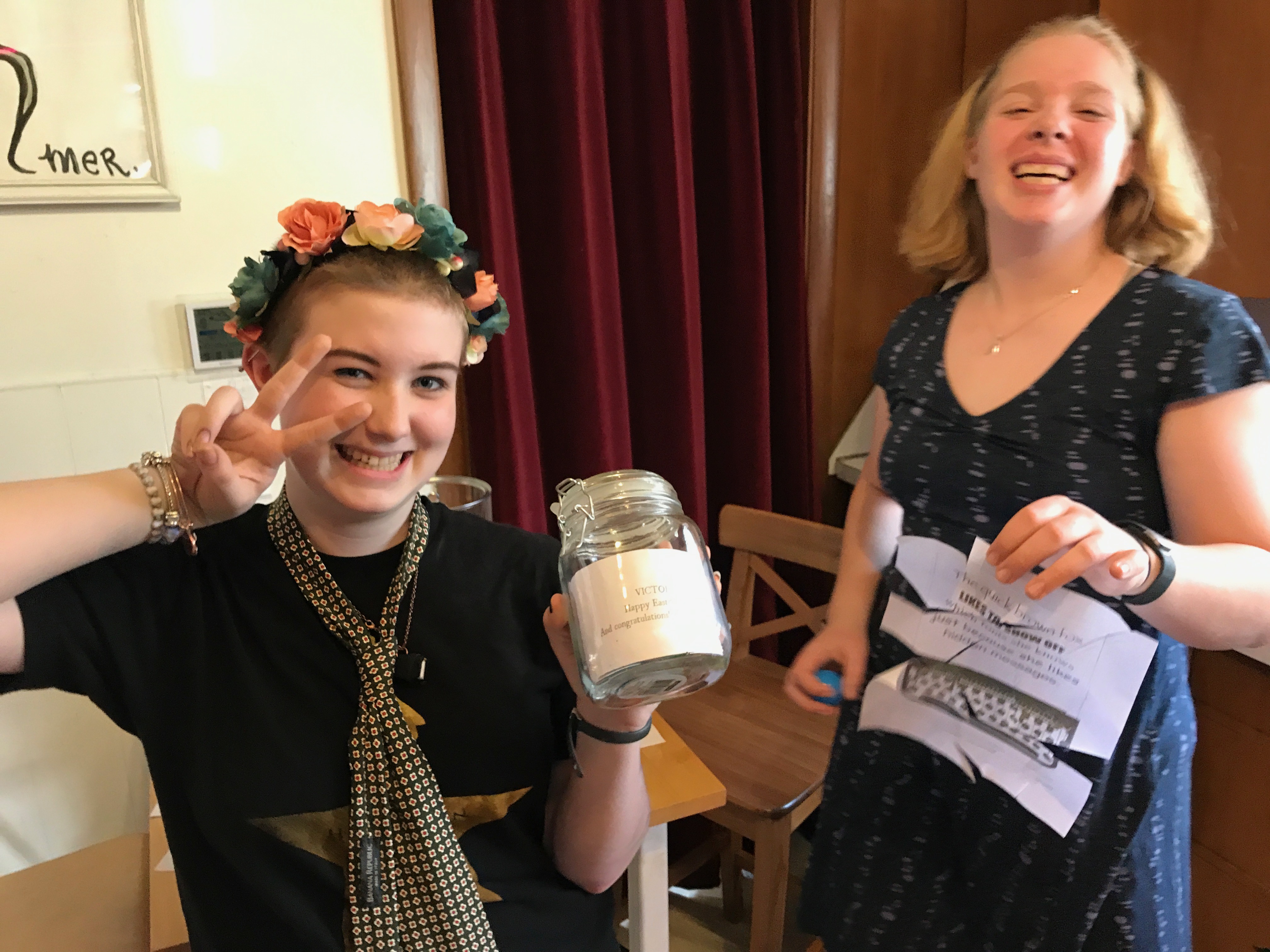
Happy congratulations were shared all around, and everyone enjoyed some of their hard-won chocolate.
With the puzzles finally solved, and chocolate fully secured, Eleanor finally stopped repeating the word “patricide” over and over, which she’d started saying nearly an hour before.
For the record, the total elapsed time was 56 minutes, 42 seconds — including the time it took for me to fix the typo in the math key (oops), and the time that Eleanor spent repeating the word “patricide”.
Maybe next year I’ll start making the puzzles hard.
#68: Clearway, For Inventing CDN
Posted: July 13, 2016 Filed under: Coding, Creations, Explorations, Getting A Clue, Reflections, That Totally Worked, Uncategorized | Tags: cdn, clearway, firesite, invention, inventions, patent, patents, startups Leave a commentBear with me here, because about 200 words from now I’m going to make a huge brag that I hardly ever talk about these days. OK, thanks. Let’s go:
In January 2001, “Web Hosting Magazine” published their “Top 100 Awards” issue.
Clearway Technologies, a company that I founded, shared an award for “Fastest Growing New Market: CDNs”. C.D.N. stands for “Content Delivery Network”, a system of helping deliver web pages, images, and videos faster over the Internet; the CDN that some people may be familiar with today in 2016 is Akamai, but back in the 2000’s, there were half a dozen CDN companies, all trying to get a slice of the CDN revenue pie.
On pages 42-43, Clearway, SolidSpeed, Speedera, EpicRealm, and Akamai were all called out for awards #5, 6, 7, 8, and 9, in the overall CDN area, and for developing this hot new marketplace.


And then, later on in the list of awards, we come to #68, given exclusively to Clearway, and to me, “For Inventing CDN”.
And you know what? They’ve got the facts right here. By the time Akamai was just barely getting started, I already had Clearway Technologies up and running, and we were already shipping our first CDN offering, and I’d already filed for the patent on our core technologies.
So while I’m a little too modest to be comfortable saying it, as far as I can tell, it’s true:
I invented the first CDN.
Now, while I do get to say that I invented the first CDN, “FireSite” and “FireSite.net”, I also have to say that I didn’t get rich from it. Clearway was initially a ‘bootstrap’ startup, and so grew very slowly at first. Here’s the entire company, in August 1996 doing our initial product launch at Macworld in Boston.

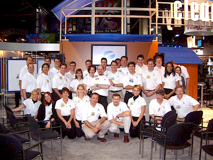
Later, we took in venture capital, and we grew Clearway to over 200 people. Here’s the team that helped do our ‘big’ launch at Networld/Interop 2000 in Atlanta.
So we grew the company and ultimately we sold it to Mirror Image Internet, another CDN company with complementary technologies and assets. And while Mirror Image is still around today, it, also, is not a success story. Mirror Image was never able to successfully monetize the union of their existing network infrastructure and Clearway’s advanced CDN technology, and so the company has never seen the growth that we hoped. (And thus I learned the meaning of the term “reverse stock split.”)
Other people have gone on to build bigger CDNs — most notably Akamai, who has become the dominant player in the CDN market, and they’re doing fine financially.
My original CDN patent (U.S. #5,991,809) was filed on July 25, 1996. In the U.S. the term of a patent is twenty years from the first priority date. That means my first CDN patent will expire in two weeks, on July 26, 2016. These twenty years have been a heck of a ride, and looking back, I’m proud of what I invented, and happy to see what it’s become.
-Mark Kriegsman, July 12, 2016.
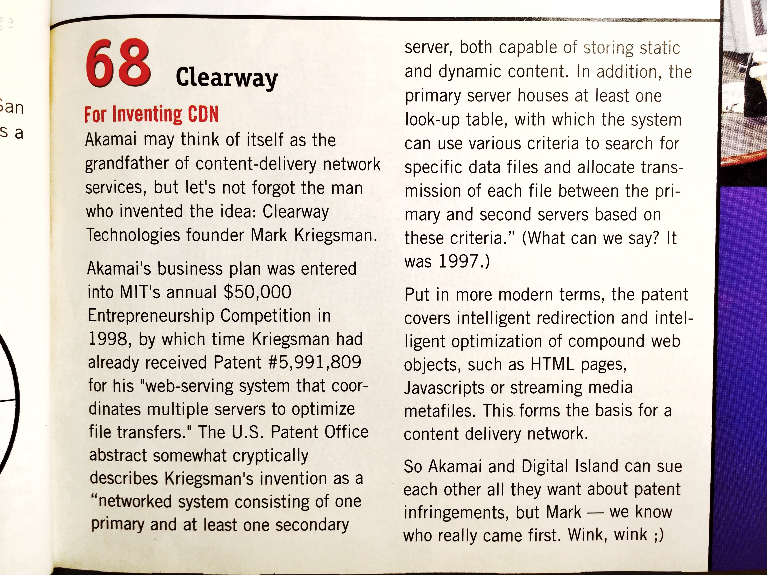
Here’s the full text of what Web Hosting Magazine had to say about the invention of the CDN:
from Web Hosting Magazine, January 2001, page 77.
#68
Clearway
For Inventing CDNAkamai may think of itself as the grandfather of content-delivery network services, but let’s not forget the man who invented the idea: Clearway Technologies founder Mark Kriegsman.
Akamai’s business plan was entered into MIT’s annual $50,000 Entrepreneurship Competition in 1998, by which time Kriegsman had already received Patent #5,991,809 for his “web serving system that coordinates multiple servers to optimize file transfers.” The U.S. Patent Office abstract somewhat cryptically describes Kriegsman’s intervention as a “networked system consisting of one primary and at least one secondary server, both capable of storing static and dynamic content. In addition the primary server houses at least one look-up table, with which the system can use various criteria to search for specific data files and allocate transmission of each file between the primary and secondary servers based on these criteria.” (What can we say? It was 1997.)
Put in more modern terms, the patent covers intelligent redirection and intelligent optimization of compound web objects, such as HTML pages, JavaScript or streaming media metafiles.
So Akamai and Digital Island can sue each other all they want about patent infringements, but Mark– we know who really came first. Wink, wink ; )
Easter Egg Hunt 2016.
Posted: March 27, 2016 Filed under: DIY, Explorations, That Totally Worked | Tags: code, codes, CTF, cypher, cyphers, Easter, easter egg hunt, easter eggs, emoji, puzzle, puzzle hunt, puzzles, QR code, QR codes, rules 1 CommentWe’ve always loved Easter egg hunts, but with the girls getting smarter, faster, and more wily every year, we’ve had to make the hunt more… challenging. Our previous Easter egg hunt had infuriatingly complex rules as to which girl got which color of egg. But with the girls in middle school now — actual teenagers — I knew that I was going to have to step up my game if I wanted the hunt to last more than just a few minutes. Inspired by some of my puzzle-crafting Veracode coworkers, I put together our 2016 Easter Egg Hunt. Here’s how it went.
Step 1. Read the rules.
Once again, Eleanor and Abby were each given a sheet of paper indicating which colors of eggs they should each pick up. Here are the ‘rules’ they were given for this year’s egg hunt:
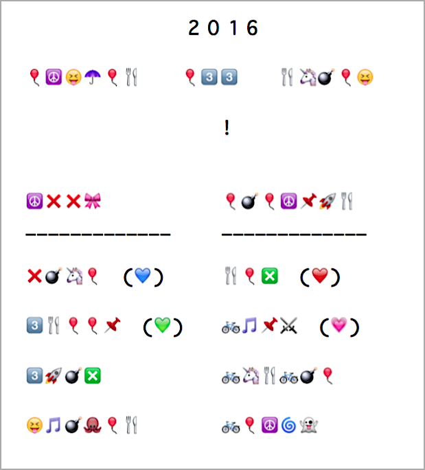
After a few false starts, the girls cracked the emoji substitution cypher. Since some symbols like🌀 and 👻 appeared only once on the page, it took some thinking to decode the whole set of color rules, but working together they did it.
Step 2. Find the eggs.
List of colors in hand, they ran outside to start finding the eggs hidden around the back yard. Each girl found all of their eggs within about ten minutes; finding the eggs themselves isn’t too terribly difficult — which is why we got into all these rules and colors and puzzles in the first place.
Step 3. Open the eggs… and wait, what’s this?
Once back inside, the girls opened the plastic Easter eggs… but wait! Where’s the loot?!? Instead of treats or trinkets, each egg held one small, oddly-shaped piece of paper with black and white squares on it: a QR code, cut into puzzle pieces.

Working quickly, the girls each assembled the pieces of their respective QR code puzzles. One went together easily, the other took some collaboration and a couple of different attempts before it all came together.

Step 4. Follow the clues.
Each girl’s QR code was different, and scanning the re-assembled QR codes led to two different URLs: two different tweets, by two different people (neither was me). Each tweet had a picture and a big clue about a different location around our house.
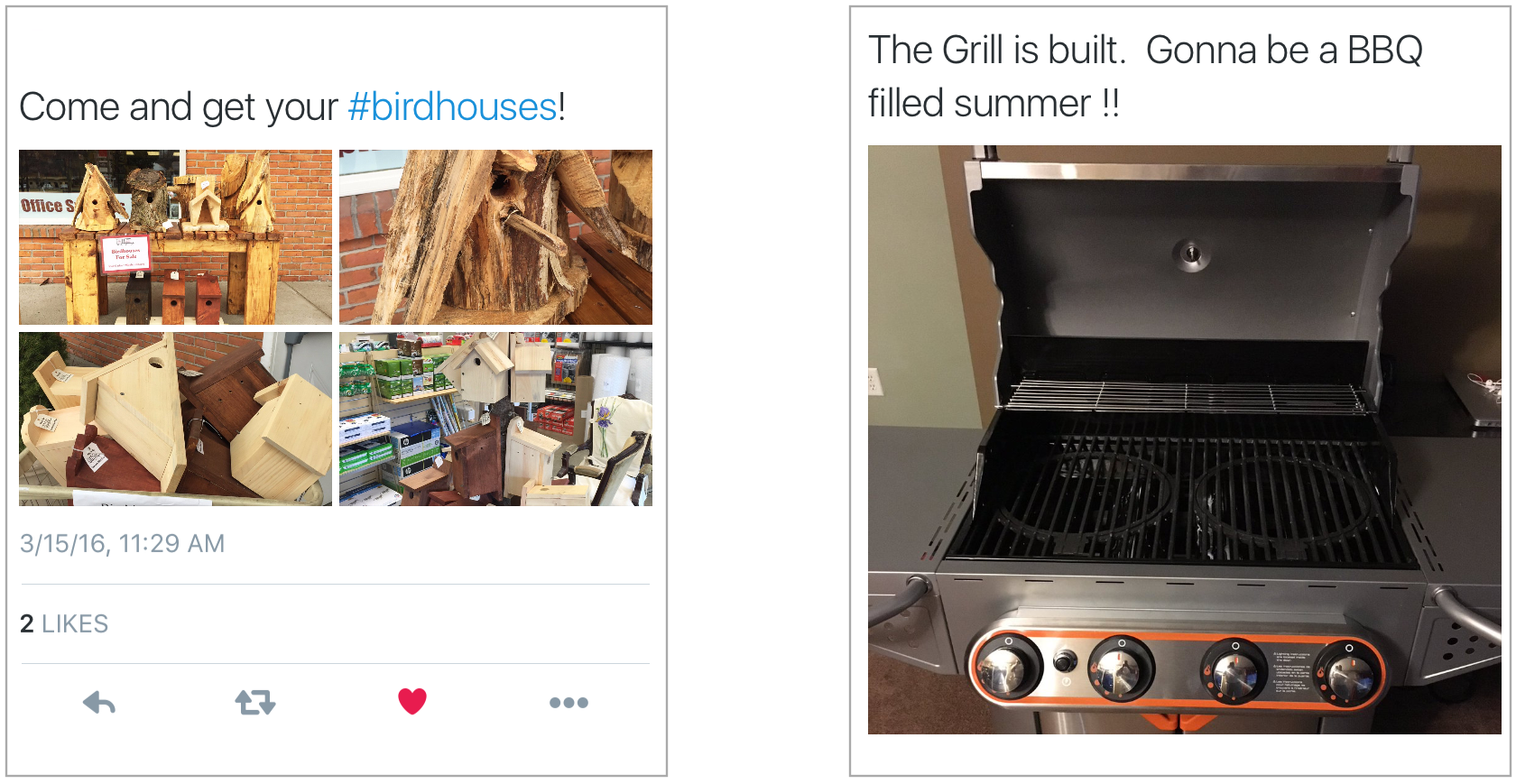
Step 5. Victory!
Eleanor dug down into our pile of birdhouses (why we have a pile of birdhouses is a long story for another day), and Abby popped open the lid of the grill. Each girl found a set of colored ‘crystal’ eggs — filled with sweet, sweet victory loot!
In just under 45 minutes, the girls had cracked a cypher, found the hidden Easter eggs, reassembled the QR code puzzles, and followed the twitter URL picture clues to find their well-deserved treasure. The chocolate was sweet, but from the looks on their faces, I think the taste of victory was even sweeter.

Now about next year…
First light – five years later
Posted: March 25, 2016 Filed under: Art, DIY, Explorations, Getting A Clue, Pearls of Folksy Wisdom, Reflections, That Totally Worked | Tags: art, blinky, fastled, journey, learning, LEDs, light Leave a commentFive years ago today I got my very first piece of LED art gear to light up for the very first time.
It was a Color Kinetics panel that you sent data to over ethernet, not an addressable LED strip & embedded microcontroller coding situation at all. The panel itself previously belonged to an LED art pioneer, “Frostbyte”, who had taken it with him on his desert adventures before his untimely and accidental demise. His old electronic gear was auctioned for charity, and without really knowing what I was getting in to, I bought this massive (28 pound!) metal box with 144 RGB LEDs in it, and the network controller to match.

I could find no open source software to drive it, and owning the commercial sequencing/design package was out of my reach. For three years, the panel sat in my workroom idle and dark. But at some point, I found that the vendor had a simple free “test program” available, and I decided to see what I could do. Since the color data was sent from the test program to the panel over ethernet, I was able to capture the network packets, reverse engineer them, write my own code to talk directly to the LED panel, and TA-DA! First light!
But even with that one LED panel up and running, more than a year passed before I started learning how to use addressible LED strips and Arduino microcontrollers. Another year after that, I had officially become ‘part of’ FastLED with Daniel Garcia.
And now? Now I’ve created LED art myself, taken it on my adventures– desert and elsewhere, sold it and gifted it. I’ve taught LED classes, and I’ve helped build an online community for thousands of FastLED users. I’m not sure what I expected when I first bought that LED panel, but I don’t think it was all this great stuff.
So if there’s a lesson here, it might be this: If something intrigues you, step toward it. You never know exactly where you’ll wind up, but the journey will be an adventure in the right direction.
Cautionary Tales of Power
Posted: November 27, 2015 Filed under: Coding, Creations, DIY, Explorations, Getting A Clue, How-to, Pearls of Folksy Wisdom, So that didn't work | Tags: arduino, blinky, DIY, fastled, fire, glow, glowy, LED, LEDs, light, power 3 CommentsWhen doing an LED electronics project, there seem to be three big “P”s that have to be tackled:
1. Pixels (which ones, how many, what configuration?),
2. Programming (what do I want, and how can I do that?), and
3. Power (how much, from where, and how do I distribute it?)
And people (by which I mean: perpetual newbies like me) tend to do them in that order: first wire up some pixels, then program them, then figure out how to power it all for real.
And of course, this often leads to a problem where you get stuck between steps 2 and 3, where you have your creation sort of up and running on the lab bench — but now there’s this little problem of how to power it, and you have to go back and rethink and rework other parts of the project to accommodate the power situation. So it’s worth planning for power from the start — which is easy to say, but hard to do!
What could possibly go wrong? (A list)
So what happens if you don’t plan for power? Well, here are some power problems that I have personally had. How many of these can you diagnose just from the description? (“Failure to plan” is a nice catch-all phrase here if you get stuck.)
- Hrm, now how do I get power all the way up there?
- Gee, that’s a long run of wire… but if I use fat wire, it’ll be expensive and heavy and cumbersome. Nah…
- I’ll use skinny wire, it’s much cheaper… Hey, why is it only reading 4v at the far end? And does anyone smell something burning?
- OK, I switched to thicker wire, and I’ll just re-use the power connectors from before. Holy cow now the connectors are getting hot!
- Fine, I’ll switch to these big thick nonpolarized connectors. Huh, that’s odd, it’s not working now. Does anyone smell something burning?
- For this other wearable project, I’ll use a simple battery holder and regular alkaline batteries… hey… why are the colors so ‘warm’.. no blue? And now no green, too…
- OK, switching power to one of those ’emergency phone chargers’ that takes AAs and puts out 5v from a USB socket. Hey! Why are the batteries dying so fast?
- OK, fine, I’ll switch to this lithium battery pack… hey, it said 5000mAh… so why did it stop powering my 5000ma project after only half an hour?
- How come my WS2811 project works fine from my computer, but then flickers like crazy when I power it from this cheap USB wall power adapter?
- For this big outdoor project, I’ll use this big, burly 12V lead-acid marine battery. Hey… how come it won’t hold a full charge after the first time I let the lights go all night?
- Everything was working fine yesterday, before last night’s rain!
- Everything was working fine yesterday in the cold and snow, so it should be working fine today now that it’s warming up, right?!
- I think I’m going to switch microcontrollers. The old one had a power regulator that could handle 12v input. Hey… do you smell something burning?
- Why is this power switch getting hot now? And why is it now totally stuck in the “on” position? And … do you smell something burning… again?
So: Plan For Power.
The lesson to learn here is that for basically any real project, calculate and plan the power first. Before you wire up any pixels. Before you write any code. Just stop for a minute and think about how much power you’re going to need, and where it has to come from, and where it has to go.
Use on-line calculators that will help you figure out how much power you’re going to need, and what gauge wire you’ll have to use given how long your cable runs are going to be. I also really like the “LEDstimator” app for iOS to help explore some “what-if” values for things like wire gauge. https://itunes.apple.com/us/app/ledstimator/id945794010?mt=8
And above all else… uh… wait… do you smell something burning?
