Calling down the lightning
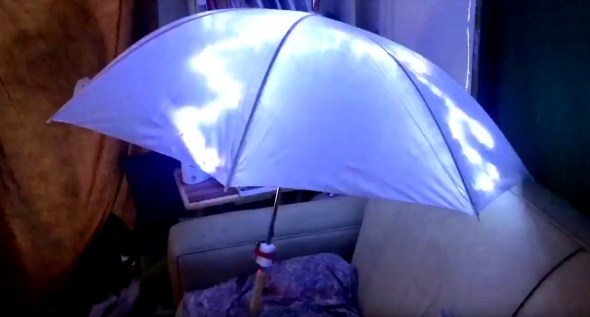
Posted: January 16, 2026 Filed under: Art, Coding, Creations, DIY, Explorations, How-to, That Totally Worked | Tags: arduino, attiny, blinky, burning man, DIY, electronics, fastled, Halloween, LED, LEDs, light, lightning, MOSFETs 2 CommentsSo here was the big idea: a bunch of umbrellas with lightning in them. Like this:
Sianna and Dean and I started brainstorming about this as an idea for an art project for Burning Man 2018, and as these things do, the idea quickly blew up from a simple idea to include all kinds of complicated and awesome details.
The original idea was something like:
- umbrellas
- plain, always-on LED strings (cool white) sewn into the umbrellas
- use the pre-wired 3xAA battery pack that comes with the LED strings
Here’s where we wound up after a bunch of brainstorming:
- umbrellas
- four independent strings of LEDs (cool white) sewn into each umbrella, so that there could be animation and motion
- microcontroller programming of the LED strings, to create the flashes and motion
- some other sort of battery setup, not just the plain 3xAA battery pack that came with each LED string
- synchronization of the whole pack of umbrellas together, so that lightning could flash across all of the umbrellas at once, or across them in some kind of fast sequence
Sianna and Dean did all the sewing of the LEDs into the umbrellas, and I did the electronics design, construction, and programming.
What follows is the story of how I arrived at the final electronics design for these “stormbrellas”. I started with an initial electronics design for each umbrella that required some kind of full Arduino board plus a custom PCB ‘shield’ with a literally a dozen discrete components on each board to drive the LED strings. Then, through some outside-the-box thinking, some semi-careful / semi-brave experimentation, and progressive refinement I wound up with a design that required a total of just three discrete components to control each umbrella — and no “Arduino” board.
I am not a big expert at this sort of electronic design project, so a great deal of this was new territory for me. I’m hoping that you find this story interesting, and that perhaps it inspires you to try something new in this area, as well.
The Naive Design
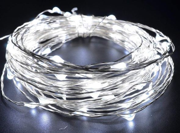
The LED strings that we were using were the kind with ‘grain-of-rice’ LEDs mounted on barely-insulated bare metal wire, like this.
I wanted to use an Arduino (of some sort) to control the strings of LEDs, because I know it pretty well, and I already had a bunch of them lying around waiting to be used in projects.
Power to the pixels
I know that you can power individual LEDs directly from the ‘output’ pins of an Arduino, by connecting the LED from the output pin, through a (very important!) current-limiting resistor, to Ground. There’s a famous sort of joke in electronics that if you omit the current-limiting resistor, the LED will try to draw more power than it can handle, and in a very short period of time it will turn from a Light-Emitting Diode into a Smoke-Emitting Diode. (See also: “light-emitting resistors”.) So you always always always need to make sure the LEDs can’t draw more power than they can handle, and the way to do that is a current-limiting resistor.
I also know that there’s a limit to how much current you can draw directly from one Arduino pin, and that you definitely cannot run a whole string of LEDs directly from an Arduino output pin. Instead, you need to use a power transistor, like a MOSFET, as a sort of a power switch. The Arduino controls the MOSFET, and the MOSFET switches the high-current power on and off to the LEDs. Each MOSFET needs a ‘pull-down resistor’ to turn it all the way off when it’s not being activated.
Of course each string of LEDs still needed a ‘current-limiting resistor’ as well. When I dissected one of the battery packs that came wired to the LED strings, I found that each one had 3xAA batteries (4.5 volts total), an on/off switch, and a 3.6 ohm current-limiting resistor, all in series with the string of LEDs. These particular LEDs seemed to want something like 3.3 volts across them. The battery pack (3xAA) produced 4.5v, and their simple design just used the small resistor to limit the current, and drop the voltage — throwing away the rest of the energy as heat. And wow did that resistor get hot!
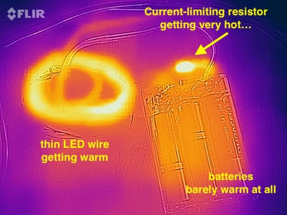
I measured the temperature of the resistor (in open air) at over 140ºF when the LEDs were lit. It was definitely keeping the LED current and voltage down, but it was throwing away a whole lot of the battery power as heat, too. I estimated that nearly 1/3rd of the energy in the batteries was being turned into heat, and only about 2/3rds of the energy was coming out as light. Anyway, clearly the current-limiting resistor was important for these LED strings.
So I figured that I’d want an Arduino board, and then for each string of LEDs, a MOSFET, a pull-down resistor, and a current-limiting resistor, arranged something like this:
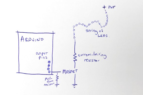
This shows the rough design for controlling one string of LEDs; to control four strings of LEDs, I’d need four MOSFETs, four pull-down resistors, and four current-limiting resistors. I figured that I’d mount all of that on some kind of Arduino ‘prototyping’ shield. Each shield would have those twelve components on it.
Call me lazy (go ahead, I’ll wait), but that seemed like a lot of parts, and a lot of work to build six umbrellas that way.
“Grandfather say ‘It never rain every day'”
I started thinking about those current-limiting resistors, and these LED strings, and about Burning Man, and about lightning itself. To simulate the look of lightning, I was not going to run these LED strings turned on all the time. In fact, they’d be turned off most of the time. I’d only need to power them up for short, bright flashes. And of course, this being Burning Man, the brighter, the better!
I also thought back to this great tech note from Cree (the superbright LED people) entitled “LED Electrical Overstress”, but which I refer to as “So You Want To Run Our LEDs Beyond Their Rated Power Limits”. http://www.cree.com/led-components/media/documents/XLamp_Elec_Overstress.pdf This tech note addresses the question “OK, so if the LED is rated for X volts, what actually happens if I run it at a voltage higher than X, but just for a short time?” And the answer they give is something like this: well, it might be a little bit brighter (but not proportionately), and it will probably also shorten the life of the LED, especially if the LED is over-volted for any significant amount of time.”
And I thought about those tiny little 3.6 ohm current-limiting resistors in the battery wired pack. I wondered if I needed them at all. Maybe I could sneak by without the current-limiting resistors — if I only pulsed the LEDs on for short flashes. And maybe, just maybe, the LEDs would flash brighter than usual, for those short flashes, if I omitted the current-limiting resistors. I decided to try it as an experiment: run the LED strings with no current-limiting resistor. Well, sort of. I say sort of because those LEDs are strung along very long, very skinny wires. And you know what a long, skinny wire acts like? Hint: a resistor.
Well, I tried running one of the LED strings for fifteen minutes solid, at full power, with no (external) current-limiting resistor and here’s what I found: the LED strings do light up a little bit brighter. The wires themselves definitely got warm, but not too hot to touch. I wouldn’t want to run them like that, full-on, for hours… but that’s not the plan. The plan is to flash them on for fractions of a second, or maybe even flicker for a couple of seconds, and then leave them off for a long stretch.
So I decided that since I was just flickering the LED strings on with (much) less than a 10% duty cycle, I could probably skip the current-limiting resistors … and get brighter flashes in return. Win-win.
And in addition to the specific component reduction (and brightness boost), this planted a seed in my head: sometimes you can go beyond the rated limits of a device, especially if you’re only doing it for a short time. Keep this in mind; it shows up again later.
Shifting away from MOSFETs
At this point the design for each umbrella is basically: Arduino + protoshield with four MOSFETS and four pull-down resistors. And of course four LED strings. I didn’t want to juggle the four separate MOSFETs, and I started wondering if there was some pre-packaged integrated circuit that basically had four MOSFETs inside it, so that I could reduce the part count from 4 MOSFETs down to one IC.
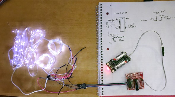
Looking around for a while, I came across the TPIC6B595, a “high power shift register”. They’re a bit like the popular 7HC595 shift register, with eight output pins, but they can drain “up to 150mA” per output pin. This might be the chip for me, I thought. But then, Hrm, I wondered, I wonder how much current I need for each LED string. I did some tests and found that each LED string could draw up to about 350mA. 350mA is far more than 150mA, so I didn’t think this chip was going work for me. On a lark, I decided to read the actual datasheet for the chip, from TI: http://www.ti.com/lit/ds/symlink/tpic6b595.pdf And look what we have here (highlighting is mine) …
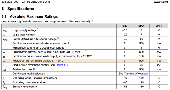
While the continuous drain current is 150mA per output pin, the peak drain current per pin is 500mA! And 500mA is greater than the 350mA that I need to flash the LED strings on for a few instants! Maybe this was the chip for me after all. I ordered one to test. Well, I actually ordered two, because electronics tend to not bounce back well from being tested with current levels above their ratings.
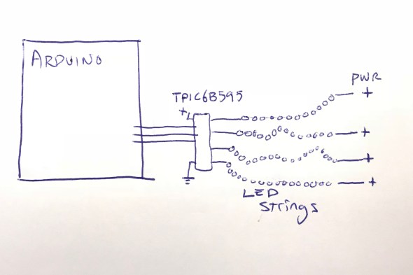
The chip arrived, and I wired it up, found some Arduino code to drive it, and lo and behold, it worked! In fact, I was able to hook up all four LED strings to the TPIC6B595 chip, and light them all up brightly (and briefly!) with no detectable overheating of the chip. I did note that the datasheet said that the whole chip could only handle one Amp (1000mA) of current. If I lit up all four LED strings at 350mA each, that would be 1400mA, more than the rated maximum current of the chip.
But again I wondered: OK, so it’s rated to handle 1000mA total. But what happens if I pulse 1400mA through it for one tenth (1/10th) of a second? Does it instantly blow up? Does it self-limit the current to 1000mA? Does it shut down and need to be powered off to reset it? Again, I decided to try it. The answer: it did not shut down, or need to be reset, or instantly blow up. In fact, it seemed perfectly happy to deliver 1400mA of current, as long as it was for short pulses, with cool-down periods between them. I decided to go forward with this, and see how far I could get. One chip, no discrete MOSFETs, and no pull-down resistors! If it worked, I liked this a lot.
Here’s where I was:
Flashdance (What A Feeling)
At this point I had a setup where I could drive all four LED strings from my Arduino code, as long as I didn’t run them all at full-blast all the time. In fact, I had to be mindful to keep the overall power level low, even if sometimes I spiked it up above the rated power level for TPIC6B595 chip, and above the standard continuous power level for the LED strings.
I spent a few hours studying ultra-slow-motion videos of lightning strikes, like this one:
After watching them over and over, I wrote and tested and refined some code that I thought created the same kind of visual impression, while also being mindful of the power envelope that I wanted to stay within. Once I had the code put together, I noticed that it was actually pretty small: compiled the code size was just about 3K, and it used less than 100 bytes of SRAM for global data. The small code and data size were hardly surprising in retrospect; in a sense, all that it did was flash four output values. I’d used FastLED’s math functions, which tend to be compact, including FastLED’s random number generator for the timing of the flashes. FastLED’s random number generator (well, pseudo-random number generator) is significantly more compact than the default Arduino random functions, which also helped reduce the code size.
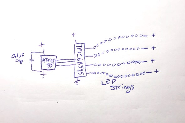
The small code size started me thinking: if I only need this tiny program, and this tiny amount of data, maybe instead of a full-blown Arduino board, I could just get away with a ‘bare’ ATtiny85 microcontroller. I knew that people did that, but I’d never done it. Luckily, there’s good documentation about how to wire up an ATtiny for programming, and good Arduino IDE support. https://github.com/SpenceKonde/ATTinyCore I decided to give this a try. I ordered a few ATtiny85s ($2.80 each) and the required (0.1uF) decoupling capacitors ($0.22 each). I used a special $15 ATtiny programmer to help simplify the programming process; I wanted to streamline the exploration of the ATtiny85 option as much as possible for myself.
When the ATtiny85s arrived, it took me a little while to get it all figured out: burning the bootloader onto the chips, and then compiling and loading my code. My original code used the Arduino SPI library to communicate with the TPIC6B595, but the ATtiny85 doesn’t have a true SPI library, so I had to adapt my code (and my head) a little bit. Also, I had written an interrupt handler routine to provide PWM dimming of the LED strips, but my code had used the TimerOne library, which is not officially supported on the ATtiny85, so I had to find an ATtiny-patched version of the library and switch to use that. https://github.com/StoykoDimitrov/TimerOne Also, due to the slower clock speed (8MHz vs standard Arduino’s 16Mhz) I had to halve the interrupt rate that I was using for my PWM support. But eventually, I got it all breadboarded up and wired and programmed, and it worked!
Here’s where I was at that point: no Arduino board, no loose MOSFETs, no pull-down resistors, no current-limiting resistors:
Everything worked great, until it didn’t
Everything worked great, even when I switched from a plug-in power supply to battery power… and then it started not working. It would start up fine, and ‘rumble’ some dim lights with no trouble, and even show the first few medium-bright lightning strikes. But on the fourth lightning strike, an extra-bright set of flashes, it would lock up. It always locked up on the fourth flash, which was always extra-bright, because the random number generator that the code used to sequence the ‘random’ flashes was, in fact, completely deterministic. Even though it might not seem that way to the casual observer, the same pattern of flashes always occurred, and the fourth one was always extra-bright, and that kept killing the microcontroller.
Based on my previous experience with battery-powered microcontroller-driven projects with lots of LEDs, I had a hunch, which turned out to be right: when the LEDs all flashed on brightly, the drain on the batteries from the bright LEDs caused an inverse voltage spike – a voltage dip. The voltage dipped too low, just for an instant, and the microcontroller locked up.
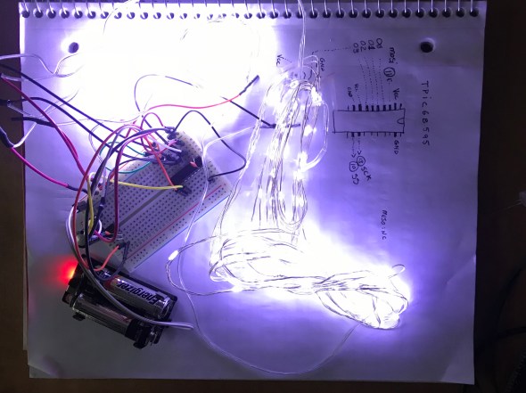
I thought about how I might isolate the microcontroller’s power from the sudden spike/dip from the LEDs flashing on full brightness. I could, of course, just reduce the maximum brightness of the LED strings, but this was a project for Burning Man, and I’m pretty sure that “reduce brightness” isn’t one of the ten principles. All I needed to do was power the microcontroller for a very short time, to bridge it across the dip caused by a very bright flash. I decided to try an experiment: I replaced the 0.1uF ‘decoupling’ capacitor ($0.22) next to the ATtiny85 with a capacitor with 10,000 times the power capacity: a 1000uF electrolytic capacitor ($1.22). My theory was that even when the LEDs spiked up in brightness, the new 1000uF capacitor would continue to provide just enough smooth power to the microcontroller it to keep running correctly. And it worked: even when bright flashes hit the LED strings, the microcontroller kept chugging along. Here’s where I was:
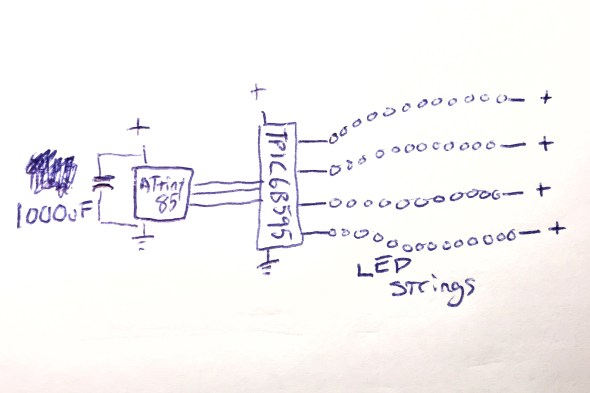
And this worked perfectly.
Now all I had to do was figure out how I was going to power this whole thing when it was mounted up inside an umbrella.
Hello Power My Old Friend
As I have written about before (see Cautionary Tales of Power), power is always a real pain in the grounding strap. Here were the choices that I was thinking about:
- 3xAA: this would be 4.5 volts on fresh batteries, and about 3.9 volts on ‘dead’ batteries. The microcontroller would probably work okay, and the LEDs would probably be okay, but I sort of felt like a 3xAA battery pack would be a little bit bulky and heavy. This was my ’emergency fallback’ plan.
- 4xAA: 6.0v on fresh batteries, 5.2v on ‘dead’ ones. I would have to use a voltage regulator, or a buck converter to drop the voltage down to the 4.5 – 5.0v range that I wanted. Plus a 4xAA battery pack would be even bulkier and heavier than the 3xAA pack above.
- Lithium Ion rechargeable battery pack: 3.7v when fully charged, 3.0v when empty. I’d probably want a boost converter to get up into the 4.5-5.0v range that I wanted. I love rechargeable batteries in general, but in the middle of the desert, there’s something to be said for being able to just eject a set of dead AAs, and drop in a fresh set. Using a lithium battery pack would make that much harder. Related options I thought about : standard 18650 cells, and also LiFePO4 cells.
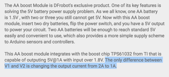
- 2xAA + boost converter: this was what I really wanted to do. I wanted to use the DFRobot “AA Boost” module, which holds two AA batteries (very firmly), has a built-in on/off switch, and a boost converter which produces 5v output. It even has a “low battery” warning LED. The whole module costs $5.90 in quantity 1, and I’ve used them many times very successfully. https://www.dfrobot.com/product-991.html
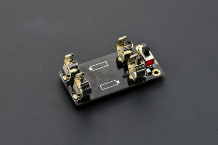
I already had some of these 2xAA+boost modules on hand, and was about ready to go forward with this plan when I spotted this in the DFRobot description. Note the current limit on the updated “V2” version of this module:
The maximum output current from this module was now just one amp. Not two, but one. One amp = 1000mA. And you may remember that the maximum power draw from the LED strings when they’re all fully lit, for a split second, is 1400mA total. And the 1400mA that we need is more than the maximum power that this module can provide.
Or… is it?
I looked up the TI TPS61032 boost chip that DFRobot uses in their boost module, and found the data sheet. http://www.ti.com/lit/ds/symlink/tps61032.pdf And while it definitely describes the chip as a “boost converter with 1000 mA current output”, look what it says in the highlighted (by me) portion of the datasheet:
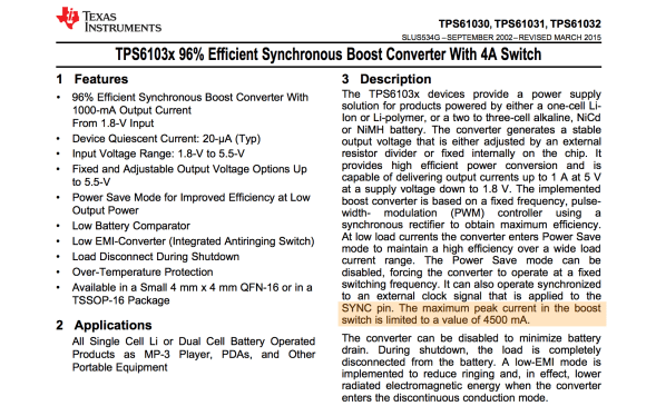
And with that datasheet in hand, I decided to do the same thing that I’d done twice before on this project: try it, and see if the components can operate over and above their advertised ‘continuous’ ratings for brief periods, with cool-down rest periods between. And the answer? Yep, short bursts above the ‘continuous’ rating seemed to work fine!
I had had a battery-life goal for the umbrellas: I wanted them to be able to run, at Burning Man, from dusk to dawn (12 hours) on one set of AA batteries. Once I had the design all wired up with the DFRobot AA boost module, I popped in a fresh set of AAs, turned it on, and went to bed. Not only was it still running the next morning, it continued to run for over 48 hours continuously, and it might have run longer, but I had to get back to work on it, so I turned it off. Next I had to figure out what I was going to do about a circuit board.
The Chairman of the Board
I’ve never designed a custom printed circuit board before by myself, and I really wanted to do that for this project. Now that the total part count for each board was down to just three (the ATtiny85, the TPIC6B595, and the 1000uF capacitor!) it seemed like a great first project for me. However, time before Burning Man was getting a little tight, and I looked around for other options that might be faster and designing a custom board, and having it manufactured for me.
Over on Tindie, I found a great little ATtiny85 Project Board for $1.75. https://www.tindie.com/products/DrAzzy/attiny85-project-board/

These little boards had: space for the ATtiny85, space for the 20-pin DIP TPIC6B595, and even a spot for the capacitor. I picked up some of these boards, added sockets for the DIP chips, seven jumper wires to inter-connect the two chips together correctly, attached some multiconductor connectors for the LED strings and power, and poof! Just look at that neat, tidy little red board there!
With all this ready to go, Sianna, Dean, and I worked out how we wanted the LED strings attached to the five-pin connectors. Sianna and Dean worked madly and mightily sewing the lights into the umbrellas, while I went into production mode, and made five more complete sets of boards and battery packs. If we’d been making more than six boards, I would have done a custom PCB for sure. Getting all those jumper wires right was my least favorite part of this project, but eventually it started going faster, and then they were all done!
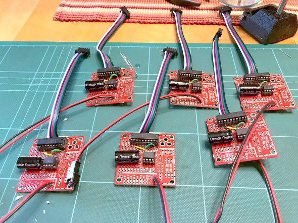
To this day, I’m still pretty proud of the three-component controller boards, and the development path that got me here.
Putting it all together
Sianna and Dean did a tremendous amount of work sewing all the LED strings into six large white umbrellas. When the first one was all put together, it was time for the first visual test. Full disclosure here: the umbrellas do not make thunder noises; the thunder noises in the following two video clips were ‘added in post’. We had thought about what it would take to make really good thunder noises, and the short answer was: a really big power supply (read: a heavy battery) and a really big (read: heavy) speaker — neither of which was going to integrate well with a umbrella intended to be carried in one hand. So: no audio. You just have to imagine the thunder noises, or, in this case, you can listen to the ones I dubbed into the video.
So here was Stormbrella #1, sitting on the couch.
And then came the whole collection, Stormbrellas #1 through #6, scattered across the living room.
For reasons of time and technology, the six of them are not wirelessly synchronized with each other, but other than that, these were just what we hoped. Sianna and Dean took a bunch of them out to Burning Man, where the umbrellas flashed their lightning, and fought mightily with the high winds in the Black Rock desert. Some of the stormbrellas even lived to return home and tell the tale of their adventures, and their victory.
Epilogue: A Halloween Thunderstorm
For Halloween, the kiddo and I always liked to decorate the front yard of our house with a big theme, like turning the house into a castle, or a discotheque, or an aquarium. And that year, we made the front yard into a thunderstorm. We set up a big sound system to play thunder, programmed flash strobes to light up the front of the whole house, and all of the stormbrellas on stands, giving lightning and umbrella vibes at the same time. Also I put a sprinkler on top of the house so that it was actually raining the tiniest bit, completely with a baffle to keep the actual front walkway up to the house — and the trick-or-treaters — dry. The overall immersive effect was great, and the stormbrellas rode again!
I still have the stormbrellas, and sometimes when it’s a rainy night out, I carry one of them as I walk, happy and dry underneath as the lightning I made flashes overhead.
Cautionary Tales of Power
Posted: November 27, 2015 Filed under: Coding, Creations, DIY, Explorations, Getting A Clue, How-to, Pearls of Folksy Wisdom, So that didn't work | Tags: arduino, blinky, DIY, fastled, fire, glow, glowy, LED, LEDs, light, power 3 CommentsWhen doing an LED electronics project, there seem to be three big “P”s that have to be tackled:
1. Pixels (which ones, how many, what configuration?),
2. Programming (what do I want, and how can I do that?), and
3. Power (how much, from where, and how do I distribute it?)
And people (by which I mean: perpetual newbies like me) tend to do them in that order: first wire up some pixels, then program them, then figure out how to power it all for real.
And of course, this often leads to a problem where you get stuck between steps 2 and 3, where you have your creation sort of up and running on the lab bench — but now there’s this little problem of how to power it, and you have to go back and rethink and rework other parts of the project to accommodate the power situation. So it’s worth planning for power from the start — which is easy to say, but hard to do!
What could possibly go wrong? (A list)
So what happens if you don’t plan for power? Well, here are some power problems that I have personally had. How many of these can you diagnose just from the description? (“Failure to plan” is a nice catch-all phrase here if you get stuck.)
- Hrm, now how do I get power all the way up there?
- Gee, that’s a long run of wire… but if I use fat wire, it’ll be expensive and heavy and cumbersome. Nah…
- I’ll use skinny wire, it’s much cheaper… Hey, why is it only reading 4v at the far end? And does anyone smell something burning?
- OK, I switched to thicker wire, and I’ll just re-use the power connectors from before. Holy cow now the connectors are getting hot!
- Fine, I’ll switch to these big thick nonpolarized connectors. Huh, that’s odd, it’s not working now. Does anyone smell something burning?
- For this other wearable project, I’ll use a simple battery holder and regular alkaline batteries… hey… why are the colors so ‘warm’.. no blue? And now no green, too…
- OK, switching power to one of those ’emergency phone chargers’ that takes AAs and puts out 5v from a USB socket. Hey! Why are the batteries dying so fast?
- OK, fine, I’ll switch to this lithium battery pack… hey, it said 5000mAh… so why did it stop powering my 5000ma project after only half an hour?
- How come my WS2811 project works fine from my computer, but then flickers like crazy when I power it from this cheap USB wall power adapter?
- For this big outdoor project, I’ll use this big, burly 12V lead-acid marine battery. Hey… how come it won’t hold a full charge after the first time I let the lights go all night?
- Everything was working fine yesterday, before last night’s rain!
- Everything was working fine yesterday in the cold and snow, so it should be working fine today now that it’s warming up, right?!
- I think I’m going to switch microcontrollers. The old one had a power regulator that could handle 12v input. Hey… do you smell something burning?
- Why is this power switch getting hot now? And why is it now totally stuck in the “on” position? And … do you smell something burning… again?
So: Plan For Power.
The lesson to learn here is that for basically any real project, calculate and plan the power first. Before you wire up any pixels. Before you write any code. Just stop for a minute and think about how much power you’re going to need, and where it has to come from, and where it has to go.
Use on-line calculators that will help you figure out how much power you’re going to need, and what gauge wire you’ll have to use given how long your cable runs are going to be. I also really like the “LEDstimator” app for iOS to help explore some “what-if” values for things like wire gauge. https://itunes.apple.com/us/app/ledstimator/id945794010?mt=8
And above all else… uh… wait… do you smell something burning?
FastLED for the Apple II: Hack to the Future!
Posted: February 16, 2015 Filed under: Art, Coding, Creations, DIY, Explorations, That Totally Worked, Uncategorized | Tags: APA102, Apple, Apple //e, Apple II, AppleII, arduino, art, blinky, CALL -151, DIY, DotStar, fastled, glow, glowy, LED, LEDs, light, LPD8806, retrocomputing, WS2801 6 CommentsThese days, I hack LEDs. I’m the co-author (with Daniel Garcia) of the FastLED library for driving tons of high speed LED pixels and strips using microcontrollers like Arduino and Teensy.
But back in the day, I hacked a lot of Apple II. I published a couple of shoot-em-up games (with Geoffrey Engelstein), all written in lovingly hand-crafted 6502 assembly language.
Finally I decided it was time to link the present to the past: to connect a hundred high-speed RGB LEDs to an Apple II, somehow, and ‘port’ our FastLED library to 6502 assembly language.
Well, I did it, and it works. My new creation, “FastLED6502”, can drive a hundred 24-bit RGB pixels at more than 30 frames per second from an Apple //e :
The Details
Here are the details of “FastLED6502”:
- “FastLED6502” is a lightweight port of FastLED’s core functions to 6502 assembly language for the Apple ][, Apple ][+, Apple //e, and Apple //gs.
- Supports APA102 / Adafruit DotStar LED strips, as well as LPD8806 and WS2801 (though those two are not fully tested yet).
- The LED strip is connected to the Apple II using the 16-pin DIP game port on the computer’s motherboard. The 9-pin DB joystick/mouse port on the back of the //c, //c+, and //gs cannot be used, as it lacks the TTL digital output signals needed to drive the LED strip.
- 24-bit FastLED Rainbow colors are included, along with FillRainbow, Random8 and a number of other useful functions from FastLED’s main library.
- Everything had to be re-written from scratch in 6502 assembly language. Luckily(?), I still remember how to do that.
- The assembly code knows the binary serial protocols for the APA102 (Adafruit DotStar), LPD8806, and WS2801 LED driver chips. Depending on which one you select, FastLED6502 transmits the LED colors in the correct protocol over the game port TTL digital output lines.
-
Considering that the Apple II sports a 1MHz 6502 so slow that even a “NOP” takestwo cycles, overall performance is pretty good: more than 30 frames per second for a 100-pixel strip.
-
Speaking of speed, or lack thereof, “three-wire” clockless LED strips such as the WS2811 NeoPixel are not supported now, nor will they ever be. The CPU is would need to be at least 20X faster to support them, and it isn’t. For that you want an Arduino or Teensy, and FastLED proper: http://fastled.io/
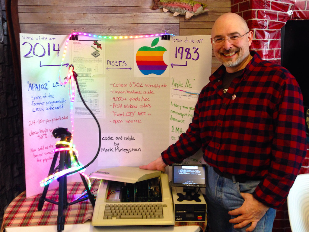
FastLED6502 at Veracode Hackathon 7
How’s it work?
So how does this all work? Well, you connect the CLOCK and DATA_IN pins from the LED strip to a couple of pins on your Apple II’s DIP game connector port, add power, and you’re ready to go. The Apple II’s game connector not only has inputs for joysticks, paddles, buttons, and so on, but it also has a few digital outputs — and that’s what FastLED6502 uses to deliver signals to the LED strip. On all the 16-pin DIP Apple II game ports (except for the //gs!), there’s even one pin that delivers a super-fast digital pulse; pin 5 is the C040STROBE line, which can pulse twice as fast as the other digital outputs. If you choose that for your CLOCK pin, the FastLED6502 code automatically shifts into high gear, and you get faster performance. FastLED proper does this, too, in a much fancier way; it’s amusing that ‘little’ FastLED6502 does some of this, too.
The Code
https://github.com/FastLED/FastLED/blob/FastLED3.1/extras/FastLED6502.s65And here’s the RainbowDemo.s65, as shown in video:
https://github.com/FastLED/FastLED/blob/FastLED3.1/extras/RainbowDemo.s65
This is Crazy
Lanyard-mountable LED throwies
Posted: May 25, 2014 Filed under: DIY, Explorations, How-to, That Totally Worked, Uncategorized | Tags: blinky, DIY, glow, glowy, invention, inventions, LED, LEDs, light, throwies, toys Leave a commentAt the last “HacKidThon”, we showed a passel of kids how to make LED “throwies”. Each one is a nothing more than an LED, a coin cell battery, and a magnet so the contraption can stick to metal surfaces, walls and buildings, and hang there glowing.
This week, someone asked me if we could modify the classic design somehow so that the LEDs could be attached to lanyards, instead of magnets. We wanted it to be as cheap and easy as the rest of the “throwie” recipe.
A little brainstorming with Eleanor, and we came up with this: plastic-coated paperclips!
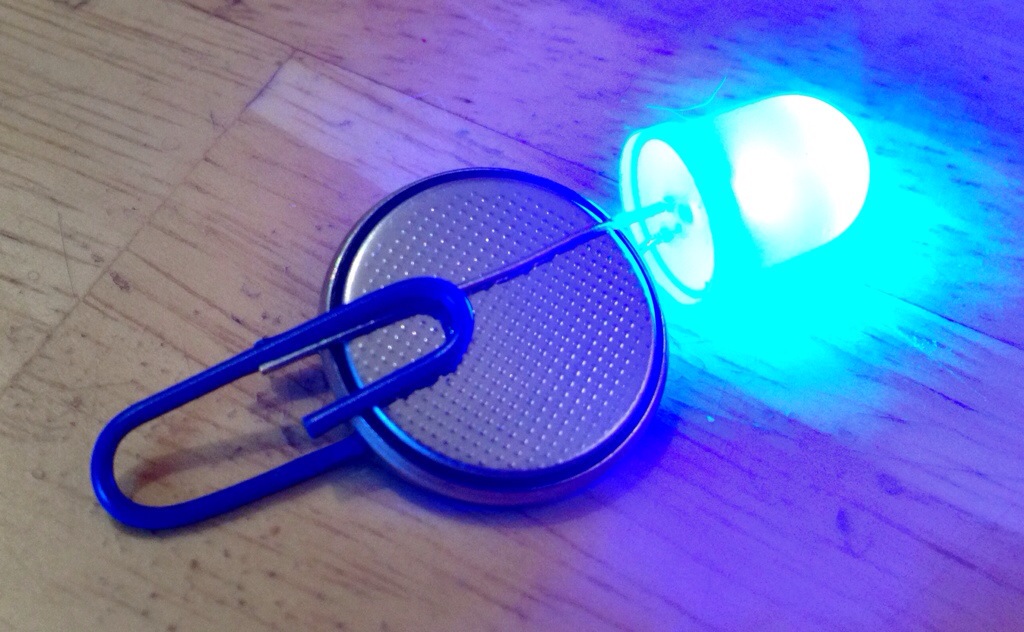
The paperclips actually help hold the LED leads in place; we put tape around them as usual, though that’s not shown in the picture. The plastic coating keeps the paperclip from shorting out the positive and negative battery terminals.
The coated paperclips cost less than a penny apiece, and come in colors that match the LEDs. Victory!
Fire2012: an open source fire simulation for Arduino and LEDs
Posted: April 4, 2014 Filed under: Art, Coding, Creations, DIY, Explorations, How-to, That Totally Worked | Tags: arduino, art, blinky, DIY, fastled, fiery, fire, glow, glowy, LED, LEDs, light 3 CommentsI’ve built and programmed a couple of different ‘fire’ simulations for Arduino and LEDs, and I’ve had numerous requests over the years to share the source code. I’ve always been happy to share my work; the holdup has been that before I share my code for the world to peer at, I like to clean it up a little. I like to give the code a clean shave and scrub under its fingernails before it steps out onto the wide open Internet where it might have an audience with Her Royal Majesty, The Queen of England. It could happen.
Anyway, I finally cleaned up the code for one of my simplest and most legible ‘fire’ simulations, and I give it to you, your Majesty, and everyone else, too. Here’s a video of the code in action on a 30-pixel strip of WS2812B LEDs (or maybe WS2811) and an Arduino. Source code link is below the video.
Full source code is here: http://pastebin.com/xYEpxqgq The simulation itself is only about 25 or 30 lines of code. It uses our (open source) FastLED library to drive the LEDs.
Discussion about the code and how to port it and use it are here on the FastLED discussion group on G+ https://plus.google.com/112916219338292742137/posts/BZhXE4cqEN4
Enjoy!
-Mark
The Lightning Tree: Halloween
Posted: November 1, 2012 Filed under: Creations, Explorations, That Totally Worked | Tags: arduino, art, blinky, DIY, fastspi, fastspiled, Halloween, LED, LEDs, light, TLT Leave a commentOver this past summer, I built “The Lightning Tree” — a 13-foot-tall steel and aluminum tree covered in hundreds of programmable LEDs. Normally, The Lightning Tree slowly cycles through animations depicting the different seasons of the year, but for Halloween I reprogrammed it full of wild purples and oranges, and planted it in our front yard!
It attracted and delighted kids and grown-ups throughout Halloween night, but the time the sun rose, it had disappeared, like all things ephemeral and magic. (To be clear: it disappeared in a good way, as Black Rock City does.)
“Five Elements” light sculpture
Posted: July 3, 2012 Filed under: Creations, DIY, Explorations, That Totally Worked | Tags: arduino, blinky, creations, decor, DIY, glow, glowy, LED, LEDs, light, RGB, sculpture 3 CommentsAfter months of work, “Five Elements”, my first full light sculpture debuted this weekend at a private event. This quick video shows a short clip of each ‘element’; the actual five-element cycle is 12 minutes long, repeating each of the five elements five times each hour. As with any “version 1.0”, I have a dozen ways I’d like to polish and keep improving it, but I’m happy with it as is, too.
It’s illuminated by 150 RGB LEDs and controlled by an Arduino Uno using the FastSPI_LED library and my own custom code.
The installation at the debut event used a very different diffuser which made the LEDs more visible. While both were good, I think I prefer this diffuser overall.
Small Scale Solar power presentation
Posted: May 1, 2012 Filed under: DIY, Explorations, That Totally Worked | Tags: 12V, blinky, DIY, electricity, glow, glowy, light, off-grid, power, repair, solar, solar cell, solar cells, solar panel, solar panels 1 CommentI gave a “learning lunch” presentation on Small Scale Solar power today. We had a great audience, got great questions, and had fun doing it — despite the definite lack of sunshine to play with today.
The Short Version is this:
- Hook a solar panel to a charge controller to a battery. (There are starter kits with everything.)
- Presto: 12 Volt DC power!
- Use your newfound power as-is, or step down to 5v USB, or up to 120VAC using an inverter.
The slides don’t tell the whole story by themselves; that requires my own personal song and dance routine. Nevertheless, here they are, with “lite” graphics for fast download: PDF.
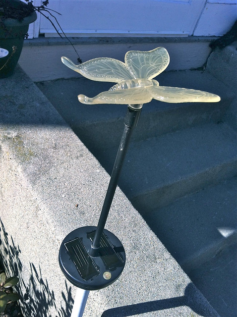
Rejuvenating solar garden lights — with nail polish!
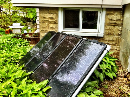
Posted: April 19, 2012 Filed under: DIY, Explorations, That Totally Worked | Tags: blinky, DIY, fix, garden, glow, glowy, LED, LEDs, light, nail polish, repair, solar, solar cell, solar cells, yard 240 CommentsSolar LED garden lights are everywhere these days, and by ‘everywhere’ I mean ‘in our yard.’ We’ve had some for a few years now, and simply through exposure to the elements, the plastic that covers the solar cells becomes so opaque that only a small amount of light gets to them any more. With the solar cells deprived of even that meager light that we get in Massachusetts in the winter, the solar cells don’t recharge the battery, the battery doesn’t power the LED, the LED doesn’t light up, and our yard has a serious bling deficiency. Eleanor and I took our solar garden lights inside to see if we could make them bright again somehow.
My first thought when confronting the frosted-over plastic was to try to ‘polish’ it with a fine-grit sandpaper. I had 400-grit handy and tried it on one cell, the bottom one in this picture. The top shows how weathered the cells were to start.

The sanding helped a little. Then I rinsed the sanded plastic dust off with water in the sink, and while it was wet it looked great, but as it dried it became frosted and opaque again. Thinking that perhaps we could use a mild plastic solvent to ‘polish’ the rough surface, I dabbed the solar cells with acetone, but again, as soon as it dried, the surface went from clear to cloudy again. “We need some way to keep it ‘looking wet’ even when it’s dry,” I mused. Eleanor got a wide-eyed LIGHTBULB! look in her eyes, and grabbed a bottle of clear nail polish! She applied a few test swatches.

The nail polish made the weathered old solar cells crystal clear again! I held the lights while Eleanor applied an even coat of nail polish to all the solar cells. It really didn’t matter whether the cells had been sanded or not, so we didn’t bother.

A few minutes later, the polish was dry, and we planted the lights outside again. You can see how completely clear the solar cells are. Our only concern was that the nail polish might block the UV light that provides a good portion of the solar energy to the cells.
We waited for twilight to fall, and when we checked the lights: success!

Even though it was mid-February the solar cells were now getting enough light to make the LEDs glow brightly! The solar cell rejuvenation project was a total success, and once we figured out how to make the cells ‘clear’ again, it was a quick and easy.
So what did we learn? We learned that ‘frosted’ plastic reflects precious light away from the solar cells; clean, clear solar cells can capture much more light. Clear nail polish is perfect for rejuvenating plastic-covered solar cells that have become weathered and dull. Some of the solar garden lights they sell have glass covers, and we speculated that they probably (1) are much more resistant to weathering, and (2) probably should be ‘cleaned’ differently from the plastic ones. Sometimes you need to try one thing to find out what you need to try next. Sometimes restating the problem out loud to someone else can give them new ideas. During the dim, dark Massachusetts winter, having bright, cheery little lights in the yard is great.
Remixed cookie cutters
Posted: March 18, 2012 Filed under: Explorations, Food, That Totally Worked | Tags: cookie cutter, cookies, DIY, food, March 17, March 17th, metalwork, remix, St. Patrick's Day 1 CommentThis past weekend E and I went out to the Berkshires to visit some longtime friends. Since St. Patrick’s Day fell on Saturday, E suggested that we all make St. Patrick’s Day cookies, and decorate them.
While the dough was being assembled, we started looking through the house cookie cutter collection for shamrocks or four-leaf clovers, but no luck. There were all kinds of other shapes, though, and twenty minutes and a pair of needle-nose pliers later, I had remixed one small cookie cutter into a shamrock, and one large cookie cutter into a four-leaf clover.

When the dough was ready, I cut a test cookie

Looking good (enough!), we baked and then decorated the cookies. The shamrock was a little bit on the small side, but the four-leaf clover came out respectably well!

That totally worked!
So What Did We Learn? We learned that metal cookie cutters can remixed and remade into new shapes. We learned that the best overall shape for a cookie is “blob”, and that “blob with minor details” is the second best shape. Fine detail doesn’t work, and remember: you’re not making stamps that will be inked and pressed onto paper: spindly tendrils of design – skinny peninsulas- don’t work. Filigree is right out. If you’re going to make a new shape out of an old one, pick an old one with roughly the same length perimeter. Small old cookie cutters make for (too) small new cookie shapes. When you start with an old cookie cutter, bend it out into a flat circle first, then work into the desired target shape. Cookies are dangerously tasty.
-Mark
